Elecraft KBPF3 User Manual
Page 13
13
Installing the KBPF3 Board on the K3 RF Board
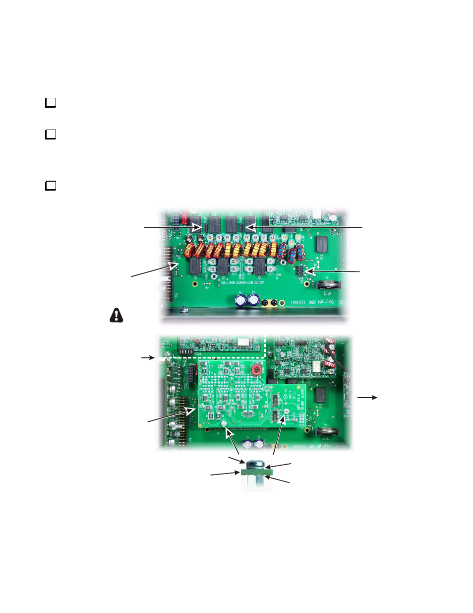
There are three connectors on the bottom of the KBPF3 board that must be properly mated to P44A, P44C and
P44E on the RF board (see Figure 12). Even though the connectors may be hard to see as they are mated,
especially if the KPA3 shield is installed, they can be aligned as follows:
Set the KBPF3 board in place over the standoffs, aligning it so the holes in the KBPF3 board are aligned
with the screw holes in the tops of the standoffs. This will align the connectors.
Press down on the KBPF3 board to mate the while checking to ensure that the holes in the board are aligned
with the holes in the standoffs. Note that simply installing the mounting screws will not ensure the 3-pin
connectors are fully mated. When properly mounted the KBPF3 board should rest on top of the standoffs and
be parallel with the RF board underneath.
Attach the KBPF3 board with a 4-40 1/4” (6.4 mm) zinc pan head screw and lock washer at each standoff
as shown in Figure 12.
NO LOCK WASHER
BETWEEN KBPF3 BOARD
AND STANDOFF
4-40 SPLIT LOCK WASHER
4-40 1/4" (6.4mm) ZINC PAN HEAD SCREW
ESD SENSITIVE!
KBPF3 BOARD
KPA3 SHIELD
(IF INSTALLED)
STIFFENER
NOT SHOWN
FRONT
OF K3
P44E
P44C
P44A
RF
BOARD
KBPF3
BOARD
Figure 12. Mounting the KPBF3 Board.