Elecraft KBPF3 User Manual
Page 10
10
Place the KRX3 main circuit board in the bottom shield so that the 1-1/2” screws extend through holes E7
and E13 on the KRX3 board. Press the KRX3 main circuit board down against the standoffs. The board will
“snap” into position as the small bumps along the edges of the board slip into the holes in the sides of the shield.
When properly positioned, the board will be against the standoffs in the bottom of the enclosure under holes E1
and E10 (the label for E10 may be partially covered by a jumper wire on the board).
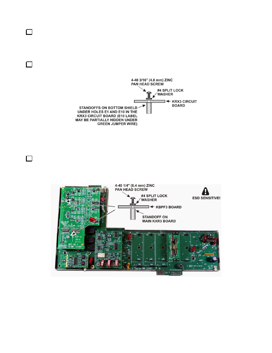
Secure the KRX3 main circuit board to the standoffs at E1 and E10 with 4-40 3/16” (4.8 mm) black pan
head screws and #4 split lock washers you removed earlier (see Figure 7).
Figure 7. Mounting KRX3 Main PC Board on Bottom Shield.
Installing the KBPF3 on the KRX3 Board
Install the KBPF3, making sure the three connectors on the bottom of the board mate with P44A, P44C and
P44E on the KRX3 board. The screw holes will line up with the standoffs when the board is positioned correctly
(see Figure 5). Secure the KBPF3 board two 4-40 1/4” (6.4 mm) pan head screws and #4 split lock washers as
shown.
Figure 8. Mounting KPBF3 on the KRX3 Board.