Caution – Elecraft KBPF3 User Manual
Page 12
12
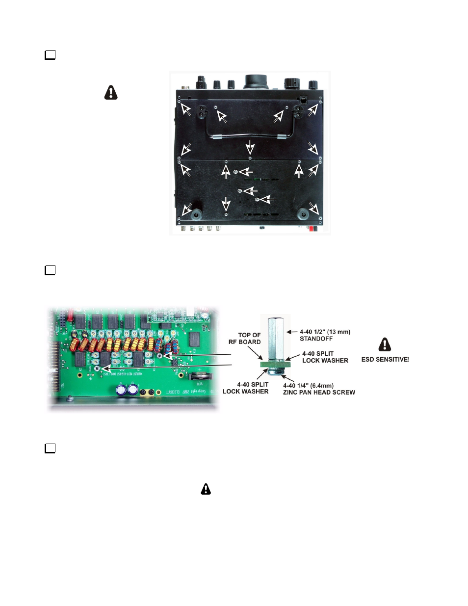
Remove both bottom covers from the K3 by removing the screws shown in Figure 10.
SEE NOTE
SEE NOTE
SEE NOTE
NOTE:
THESE THREE SCREWS
ARE 1/4" (6.4 mm) LONG
AND HAVE INSIDE TOOTH
LOCK WASHERS UNDER
THE SCREW HEADS.
ALL THE OTHER SCREWS
ARE 3/16" (4.8 mm) LONG
AND HAVE NO LOCK
WASHERS.
REMOVE ALL THE
SCREWS INDICATED
AND LIFT THE
BOTTOM COVERS
OFF.
ESD SENSITIVE!
WEAR A GROUNDED
WRIST STRAP OR TOUCH
AN UNPAINTED METAL GROUND
BEFORE HANDLING THE RF BOARD.
Figure 10. Removing K3 Bottom Cover.
Install two 1/2” (13 mm) standoffs on the RF board as shown Figure 11.Use the hardware exactly as shown.
The lock washer between the standoff and the pc board is very important to establish the correct height above
the board.
Figure 11. Installing KBFP3 Standoffs.
Replace both bottom covers using the 4-40 black pan head screws you removed earlier. Note that three
locations take the 4-40 1/4” (6.4 mm) black pan head screws with lock washers as shown in Figure 10 while the
remainder are 4-40 3/16” (4.8 mm) screws . Be sure these are in the correct locations!
CAUTION!
Failure to replace the three 1/4” (6.4 mm) bottom screws with their lock washers in
the locations shown in Figure 10 may destroy power transistors in your K3!