Elecraft KXPD1 User Manual
Page 4
4
Remove the insulation from 2" (5 cm) of the insulated wire. Cut it into two 1" (2.5 cm) lengths.
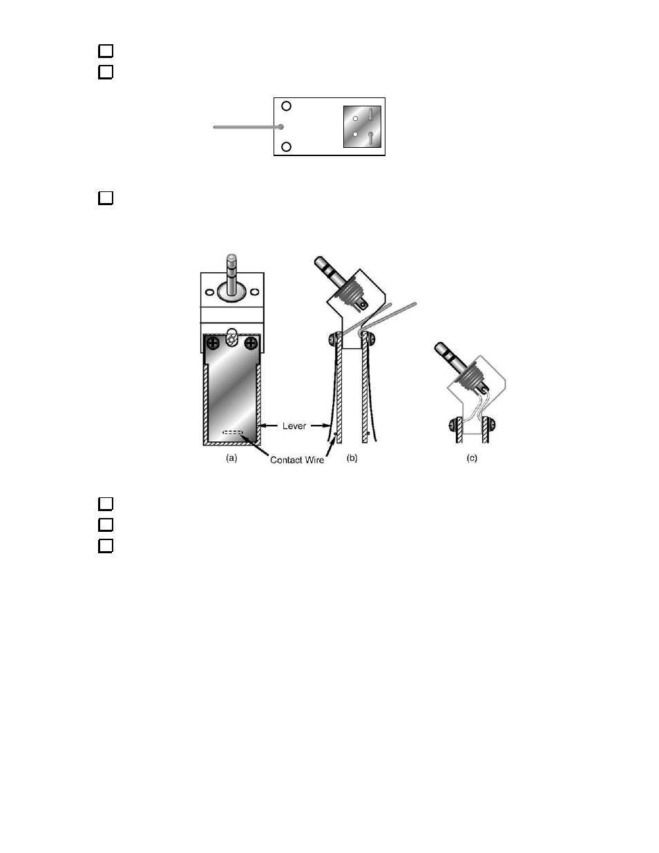
Attach one wire to each PC board at the pad shown in Figure 4. Solder on the opposite side.
KXPD1 REV B
Figure 4
Attach the levers and PC boards to the bracket as shown in Figure 5. For now, position the wires as
shown in Figure 5b, within the channel provided in the bracket. Use four 4-40 x 3/16" (4.8 mm) pan-head
screws and four split lock washers. Do not over tighten the hardware.
Figure 5
If the levers are not aligned with the PC boards, loosen the screws and re-position them.
Route the wires toward the plug's terminals and attach them as shown in Figure 5c.
Adjust the positions of the wires carefully so they are not contacting the bracket, the PC boards, or
each other. Then solder the two wires. Note: The wire originating from the PC board on the right in (c)
above should be soldered to the center terminal.
- KX3 Owner's Manual (58 pages)
- KX3 Assembly Manual (47 pages)
- KX3 Assembly Manual Errata (5 pages)
- KX3-2M (30 pages)
- KX3-PCKT (2 pages)
- KX3 Mobile Installation And Operation Guide (17 pages)
- KX3 Guide for Blind Operators (7 pages)
- KX3 Quick Reference (2 pages)
- K3 Programmers Reference (26 pages)
- KX3 Speaker Grille Instructions (9 pages)
- KXFL3 Filter Option (12 pages)
- KXFL3 Filter Option Errata (2 pages)
- KXAT3 (5 pages)
- KXBC3 (13 pages)
- KXPD3 (4 pages)
- Proset Boom Headset (1 page)
- PX3 Owner's Manual (53 pages)
- PX3 Owners Manual Errata (2 pages)
- KXPA100 Manual (55 pages)
- KXPA100 Assembly Manual (27 pages)
- KXPA100 Assembly Errata (1 page)
- KXPA100 Programmers Reference (24 pages)
- KXAT100 Installation Manual (17 pages)
- KX1 Manual (96 pages)
- KXAT1 (12 pages)
- KXB30 (8 pages)
- KXB3080 (20 pages)
- K1 (91 pages)
- K1 1.09 F/W (1 page)
- KNB1 Manual (8 pages)
- KAT1 Manual (15 pages)
- KFL1-2 (2 pages)
- KTS1 (1 page)
- KBT1 Manual (8 pages)
- KBT1 Manual Errata (2 pages)
- K1BKLTKT LCD Mod Kit (6 pages)
- K2 Owner's Manual (171 pages)
- K2 Owner's Manual Errata (1 page)
- K2 PLL (4 pages)
- K2ATOBKIT (15 pages)
- K2ATOBKT (2 pages)
- K2 Keying Modification Instructions (4 pages)
- KPA100 Manual (74 pages)
- KPA100 Shield Upgrade (3 pages)