Frame installation – EFCO 526 Series User Manual
Page 30
EFCO 6/2012
Page 30
Series 526 Impact Installation Instructions
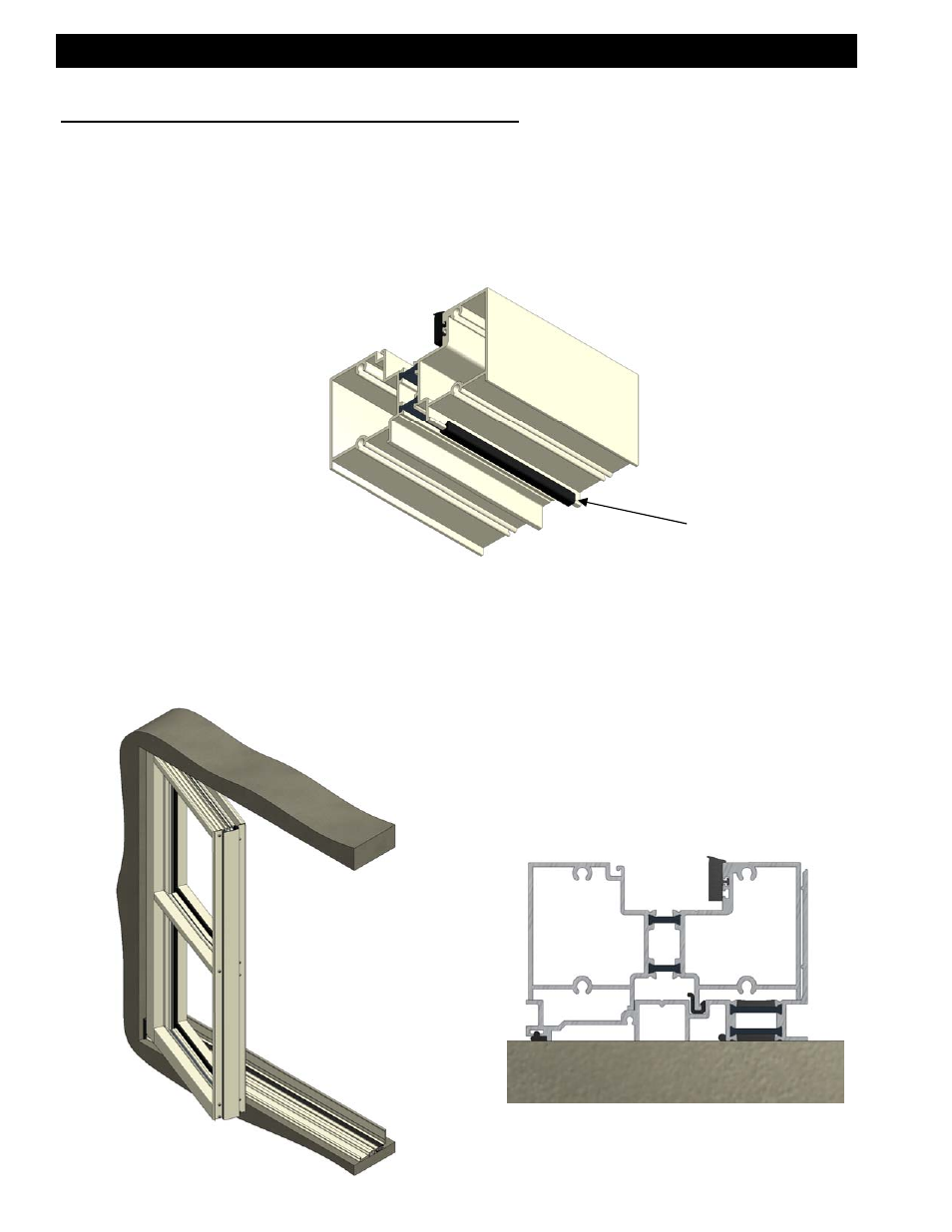
[Fig. 21]
Sill isolator placed at
1/4 points and held in
place with sealant.
Before installing the jamb module into the opening, the sill isolator (HC03) must be in
place. Slide the isolator onto the interior interlock leg on the sill. See figure 21 below.
There will need to be one at each end of the sill at quarter points. Place a small amount of
sealant on the interlock leg at the quarter point location to hold the isolator in place while
installing the module.
SECTION VII: Frame Installation
Step 1) Installing Sill Isolator
Step 2) Installing Jamb Module
[Fig. 22]
Place the module on the subsill at an approximate 30° angle. While applying pressure
upward, rotate the module into the condition. See figure 22. When rotated correctly into
place, the interlocking legs of the sill will set inside the lock cavity of the subsill; the sill
should set flat on the subsill. See figure 23 for sill placement on the subsill.
[Fig. 23]