Step 10) splicing the subsill – EFCO 526 Series User Manual
Page 29
EFCO 6/2012
Page 29
Series 526 Impact Installation Instructions
SECTION VI: Subsill Fabrication and Installation
Step 10) Splicing the Subsill
Verify that the subsills have been installed according to instructions on pages 24-28.
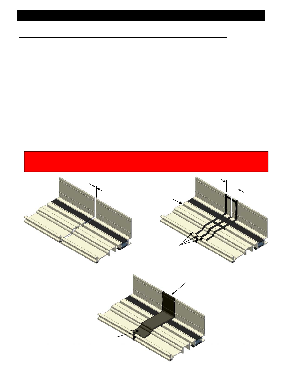
Splice areas should be centered at the vertical mullion only. Subsill length should never
exceed 20-25 feet. If a splice is required, leave a 1/4" gap between the subsill ends cen-
tered on a vertical mullion location. See figure 18. Use silicone type sealant and a strip of
WM01, bond breaker tape, 2" wide and approximately 7 1/2" long to create the splice ma-
terial. Apply the sealant to both sides of the subsill ends, fill the void between the subsills
from the exterior to the interior at the condition, and fill the sill leg receptor cavities on both
subsills to a width of 2". See figure 19. Ensure that the bond breaker tape is centered
over the 1/4" gap, and set the bond breaker tape in the sealant. See figure 20. Tool the
sealant over the bond breaker tape to create a watertight seal. If more sealant is required
to cover the edges of the bond breaker tape, apply the required amount. Ensure that the
splice joint does not interfere with anchor legs of the sill or the leg receptors of the subsill.
This is done by making sure the splice joint is located at the center of a vertical mullion.
Refer to the shop drawings or architectural drawings for mullion center lines.
1/4
2”
[Fig. 18]
[Fig. 19]
After splice tape is in
place, apply a cosmetic
seal along the 1/4” gap
at the interior of subsill.
WM01 Splice Tape
Sill Leg Cavity
Sealant
[Fig. 20]
Prior to applying sealant to the required areas, clean the area with Isopropyl Alcohol and a clean towel
that will not leave towel materials behind. Wipe off material with a sufficiently dampened towel to remove
all dust, oil, and cutting fluids from the required areas. Allow to air dry before applying any sealant.