Setting block locations, Step 2) setting block locations – EFCO 525 Series User Manual
Page 38
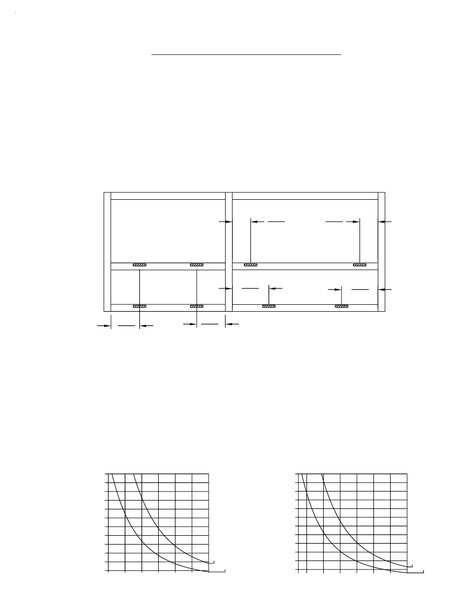
4483/4484 DOOR HEADER DEAD LOAD
100
90
120
110
40
30
70
60
50
80
10
20
4491 HORIZ. DEAD LOAD
.125 Deflection
Glass Width (in inches)
80
90
100
110
120
30
40
50
60
70
10
20
Glass Height (in inches)
[FIG. 57]
60 70
90
80
[FIG. 56]
1/4 Point
110
100
120
1/8 Point
Glass Height (in inches)
[FIG. 58]
Glass Width (in inches)
.0625 Deflection
90
70
55 60
80
110
100
1/8 Point
120
1/4 Point
SECTION IX - GLAZING
PAGE 36
(CONT.)
Depending on the size and configuration of each DLO, the glass setting
blocks must be placed to give the best support of the glass without adding
dead load weight to deflect the horizontal. Figure 56 below shows typical
1/4 point and 1/8 point setting block locations. Contact EFCO Structural
Engineering for blocking requirements other than 1/4 and 1/8 points.
STEP 2) SETTING BLOCK LOCATIONS
Setting block locations should be determined by following the Dead Load
Charts shown in figures 57 and 58 below. These charts are for general
reference only and refer to laminated glass constructed from (2) 1/4" glass
panes and laminate material. If the glass size you require falls outside the
parameters of these charts or if your glass is not constructed from (2) 1/4"
panes of glass and laminate material, please contact EFCO Structural
Engineering.
525 IMPACT
DLO
4
DLO
4
DLO
8
DLO
4
DLO
4
DLO
8
DPS 1/2004