Screw applied transom stop application, Step 6) screw applied transom stop application, Step 7) transom glass installation – EFCO 525 Series User Manual
Page 20
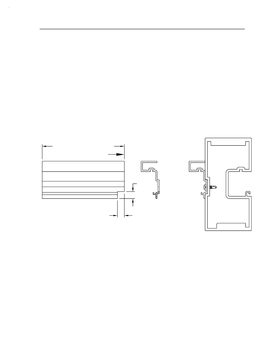
[FIG. 17]
SECTION VI - DOOR FRAME INSTALLATION
[FIG. 16]
DPS 1/2004
(CONT.)
PAGE 18
4478
4487
4487
BOTTOM OF TRANSOM STOP
STEP 6) SCREW APPLIED TRANSOM STOP APPLICATION
The screw applied vertical transom glass stops should be cut to fit
between the top of the door header and the bottom of the transom head.
The stop should be attached with STT6 TEK screws 2" from each end and
9" on center Maximum. To facilitate the installation of the door header
glass stop, a 3/8" X 3/8" notch must be made on the bottom of the screw
applied transom stop. See figures 16 and 17 below for notching and
application of the screw applied transom stop.
STEP 7) TRANSOM GLASS INSTALLATION
After the screw applied transom stop is applied, the glass can be
installed into the DLO. However, it may be advantageous to wait until
all frame installation is complete before the glazing is installed. Glazing
the transom at a later time may keep the glass from being broken while
other trades use the entrance area. Side loading is not required to
install the glass. It only has to be centered into the DLO and lifted into
the transom head so the setting blocks can be placed. See the dead
load charts listed in figure 58 on page 36 for setting block locations.
TRANSOM STOP CUT LENGTH
525 IMPACT
3/8"
3/8"