Dynojet Compressed Air Air/Fuel Ratio Module User Manual
Page 26
Compressed Air Air Fuel Ratio Module Installation and User Guide
C H A P T E R 2
Air Pump Maintenance and Troubleshooting
2-10
4
Remove the sensor(s) from the sensor block.
5
Remove the sensor block.
6
Remove the silicon tube from the sensor block.
7
Loosen the vacuum generator lock nut.
8
Remove the vacuum generator exhaust port and venturi body.
9
Unscrew the venturi body from the solenoid.
10 Use a solvent to carefully clean the vacuum generator exhaust port, venturi body,
and sensor block.
Note: Be careful not to damage the internal structure of the venturi body.
11 Secure the solenoid to the venturi body.
12 Install the vacuum generator exhaust port to the venturi body.
13 Secure the sensor block to the pump housing using the two screws removed
earlier.
14 Install the sensor(s).
15 Replace the silicon tube between the sensor block and the venturi body.
16 Replace the silicon tube to the sensor block.
17 Re-calibrate the pump using the flow meter. Refer to page A-5 for more
information.
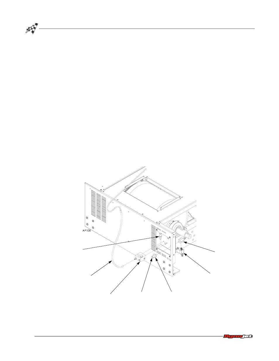
Figure 2-8: Pump Maintenance—On Dyno Pump
lock nut
vacuum generator
exhaust port
venturi body
sensor block
sensor
silicon tube
solenoid