Installing the pump assembly on the stand – Dynojet Compressed Air Air/Fuel Ratio Module User Manual
Page 13
A I R F U E L R A T I O M O D U L E A N D C O M P R E S S E D A I R P U M P I N S T A L L A T I O N
Compressed Air Pump Assembly
Version 5
Compressed Air Air Fuel Ratio Module Installation and User Guide
1-9
I
NSTALLING
THE
P
UMP
A
SSEMBLY
ON
THE
S
TAND
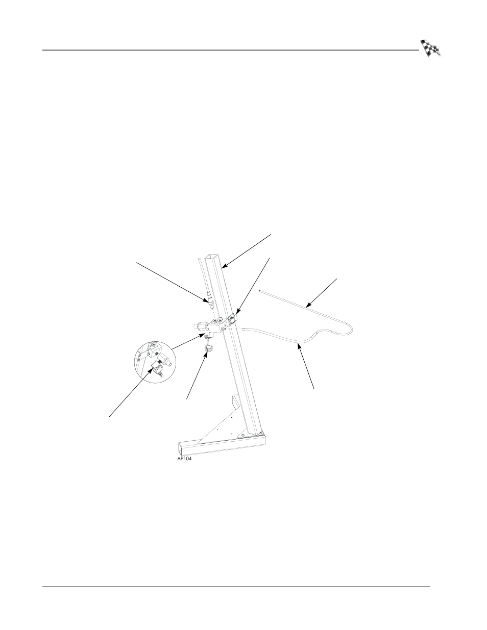
Use the following instructions to install the pump assembly on the stand. Refer to
Appendix A for on-board dyno installation instructions.
1
Open the toggle clamp and slide the pump assembly on the upright.
2
Close the toggle clamp to secure the pump in place.
3
Secure the sensor(s) to the pump assembly.
Note: Make sure the sensor is on top.
4
Attach the compressed air line to the solenoid.
Note: The compressed air must be clean and dry, 100 psi or greater.
5
Attach the silicone tube(s) to the sensor block.
Note: The length of the silicone tube can be adjusted for your application.
6
Attach the copper sample tube(s) to the silicone tube(s).
Figure 1-6: Installing the Pump Assembly on the Stand
sensor
attach compressed air
toggle clamp
upright
silicone tube
attach power cable
copper sample tube