Compressed air pump assembly, Compressed air requirements, Setting up the stand assembly – Dynojet Compressed Air Air/Fuel Ratio Module User Manual
Page 12
Compressed Air Air Fuel Ratio Module Installation and User Guide
C H A P T E R 1
Compressed Air Pump Assembly
1-8
. . . . . . . . . . . . . . . . . . . . . . . . . . . . . . . . . . .
COMPRESSED AIR PUMP ASSEMBLY
This section describes how to set up the compressed air pump assembly. Refer to
Appendix A for on-board dyno installation instructions.
C
OMPRESSED
A
IR
R
EQUIREMENTS
The following requirements are needed for the compressed air pump assembly:
• Clean and dry air, 100 psi or greater, 5 CFM or better flow
• 1/4-inch NPT pipe thread connector (to attach air to the solenoid or pump ball
valve)
• optional air regulator
S
ETTING
U
P
THE
S
TAND
A
SSEMBLY
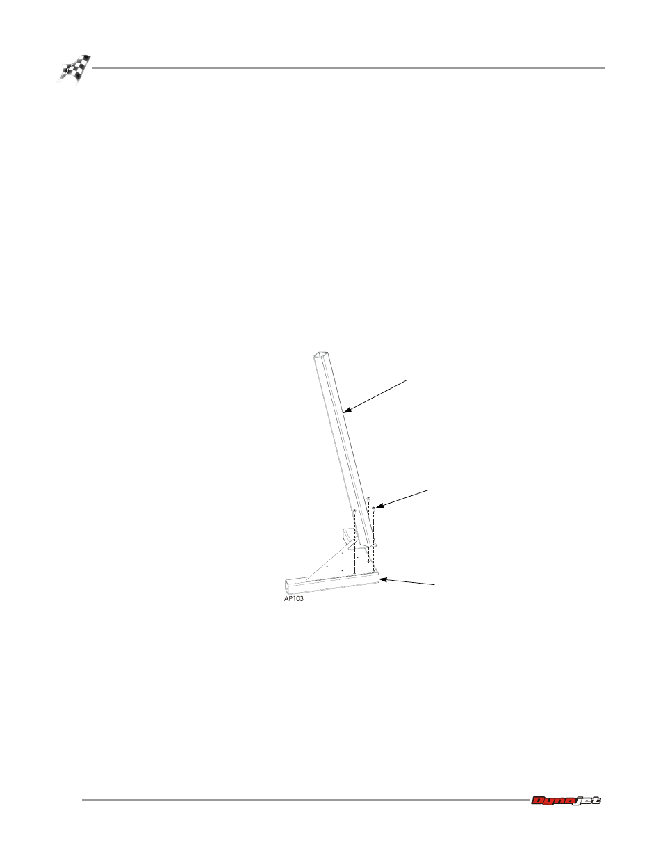
Secure the upright to the base using three 1/4-20 x 5/8-inch pan-head torx screws.
Figure 1-5: Stand Assembly
upright
screw
base