Module and pump set up – Dynojet Air Fuel Ratio Module User Manual
Page 12
Air Fuel Ratio Module Installation and User Guide
C H A P T E R 2
Module and Pump Set Up
2-2
. . . . . . . . . . . . . . . . . . . . . . . . . . . . . . . . . . .
MODULE AND PUMP SET UP
This section describes the set up procedures for the Air Fuel Ratio Module and Air
Pump Assembly.
1
Run the vehicle and allow the vehicle to warm up. Excess condensed water is
produced during warm up which can damage the Air Pump Assembly. Allowing
the vehicle to warm up removes this excess water.
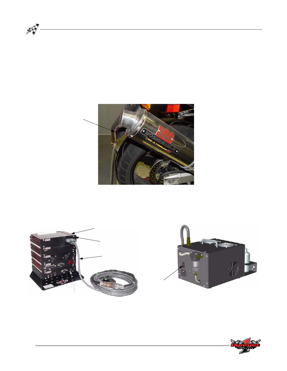
2
Place the copper sample tube in the exhaust pipe of the test vehicle.
Figure 2-1: Sample Tube Placement
3
Turn on the dyno electronics power. Verify the Air Fuel Ratio Module power
light is on.
4
Turn on the Air Pump Assembly power.
Note: Always keep the pump assembly in the upright position.
Figure 2-2: Dyno Electronics and Air Pump Assembly Power
copper sample
tube
sensor cable
power light
power
air fuel ratio
module
power