Room layout-in ground model 424xlc2 dyno – Dynojet 424xlc2: Pre-Installation Guide User Manual
Page 46
Pre-Installation Guide for Model 224 and 424 Automotive Dynamometers
D Y N O P R E - I N S T A L L A T I O N I N F O R M A T I O N
In Ground Model 424xLC
2
Dyno
38
R
OOM
L
AYOUT
—I
N
G
ROUND
M
ODEL
424
X
LC
2
D
YNO
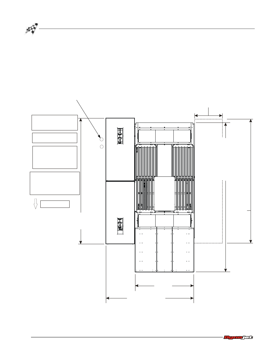
Use the following information to locate the necessary dyno equipment, power outlets,
compressed air, and properly set up your dyno room.
For more detailed information about the pit requirements, refer to the pit
specifications (P/N 98219111) you received from your salesman.
The eddy current brake is set up to run on the right side of the vehicle.
Figure 25: Room Layout—In Ground Model 424xLC
2
Dyno
492.76 cm
(194.00 in.)
eddy current brake
pit covers
229.87 cm
(90.50 in.)
345.44 cm (136.00 in.)
584.20 cm (230.00 in.)
frame and covers full out
609.60 cm (240.00 in.)
full out with bridge
extension
469.90 cm (185.00 in.)
frame and covers full in
495.30 cm (195.00 in.)
full in with bridge
extension
provide two 240V outlets
for the eddy current brakes
locate the following items
close to the vehicle:
•dyno electronics
•computer
•monitor
provide 110V outlets for the:
•hydraulic motor
•computer
•monitor
•dyno electronics
provide compressed air:
•to release the air brake
•to run the AFR-4 air pump
AD444
Linx option
492.76 cm
(194.00 in.)
Linx option
118.75 cm
(46.75 in.)
front of dyno
pit conduits