Room layout-above ground model 224xlc with lift – Dynojet 424xlc2: Pre-Installation Guide User Manual
Page 23
D Y N O P R E - I N S T A L L A T I O N I N F O R M A T I O N
Above Ground Model 224xLC Dyno
Version 5
Pre-Installation Guide for Model 224 and 424 Automotive Dynamometers
15
R
OOM
L
AYOUT
—A
BOVE
G
ROUND
M
ODEL
224
X
LC
WITH
L
IFT
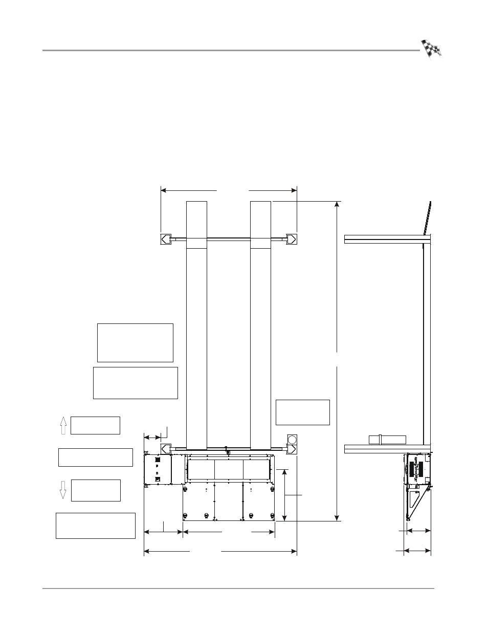
Use the following information to locate various dyno equipment, power outlets,
compressed air, and properly set up your dyno room.
For optimal eddy current brake cooling, the brake should turn in the direction of the
arrows on the rotor. The dyno will perform correctly in either direction, but cooling of
the rotors may be less effective when turning in the direction opposite of the arrows.
The eddy current brake is set up to run on the right side of the vehicle type (front/rear
wheel drive) you test most often. If this does not work for your dyno room, contact
Dynojet. Figure 7 shows a front wheel drive setup.
Figure 7: Room Layout—Above Ground Model 224xLC with Lift
798.00 cm
(314.25 in.)
128.37 cm
(50.54 in.)
228.60 cm
(90.00 in.)
382.27 cm
(150.50 in.)
97.48 cm
(38.38 in.)
42.19 cm
(16.61 in.)
58.42 cm
(23.00 in.)
65.58 cm
(25.82 in.)
AD437
provide 110V outlets for the:
•computer
•monitor
•dyno electronics
provide one 240V outlet
for the eddy current brake
locate the following items
close to the vehicle:
•dyno electronics
•computer
•monitor
provide one 240V
outlet for the lift
power unit
338.00 cm
(133.00 in.)
provide compressed air:
•to release the air brake
•to run the AFR-4 air pump
front of dyno
rear wheel drive
front of dyno
front wheel drive
shown here