Dynojet 424xlc2: Pre-Installation Guide User Manual
Page 41
D Y N O P R E - I N S T A L L A T I O N I N F O R M A T I O N
Above Ground Model 424xLC
2
Dyno
Version 5
Pre-Installation Guide for Model 224 and 424 Automotive Dynamometers
33
R
OOM
L
AYOUT
—A
BOVE
G
ROUND
M
ODEL
424
X
LC
2
D
YNO
WITH
L
IFT
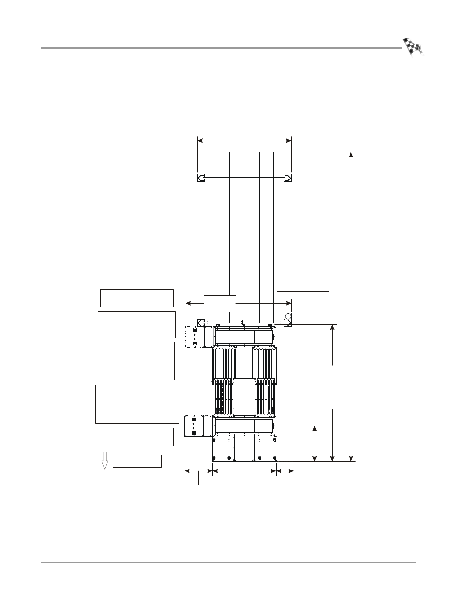
Use the following information to locate the necessary dyno equipment, power outlets,
compressed air, and properly set up your dyno room.
The eddy current brake is set up to run on the right side of the vehicle.
Figure 21: Room Layout—Above Ground Model 424xLC
2
Dyno with Lift
228.60 cm
(90.00 in.)
provide 110V outlets for the:
•hydraulic motor
•computer
•monitor
•dyno electronics
provide one 240V outlet
for the eddy current brake
locate the following items
close to the vehicle:
•dyno electronics
•computer
•monitor
provide one 240V
outlet for the lift
power unit
128.37 cm
(50.54 in.)
provide one 240V outlet
for the eddy current brake
495.30 cm
(195.00 in.)
standard
520.70 cm
(205.00 in.)
extension
382.27 cm
(150.50 in.)
1127.80 cm
(444.00 in.)
standard
1153.20 cm
(454.00 in.)
extension
338.00 cm
(133.00 in.)
provide compressed air:
•to release the air brake
•to run the AFR-4 air pump
AD443
97.48 cm
(38.38 in.)
Linx option
50.80 cm
(20.00 in.)
front of dyno