Cpu module, Cpu module -5 – Dynojet 224/4WD: Installation Guide User Manual
Page 53
D Y N O E L E C T R O N I C S
Dyno Electronics
Version 3
In Ground Model 224 4WD Automotive Dynamometer Installation Guide
3-5
CPU M
ODULE
The CPU module contains a 32-bit processor which acquires data from the expansion
modules and communicates to the main computer running the WinPEP software. The
processor queries the expansion modules to determine their identity and capabilities.
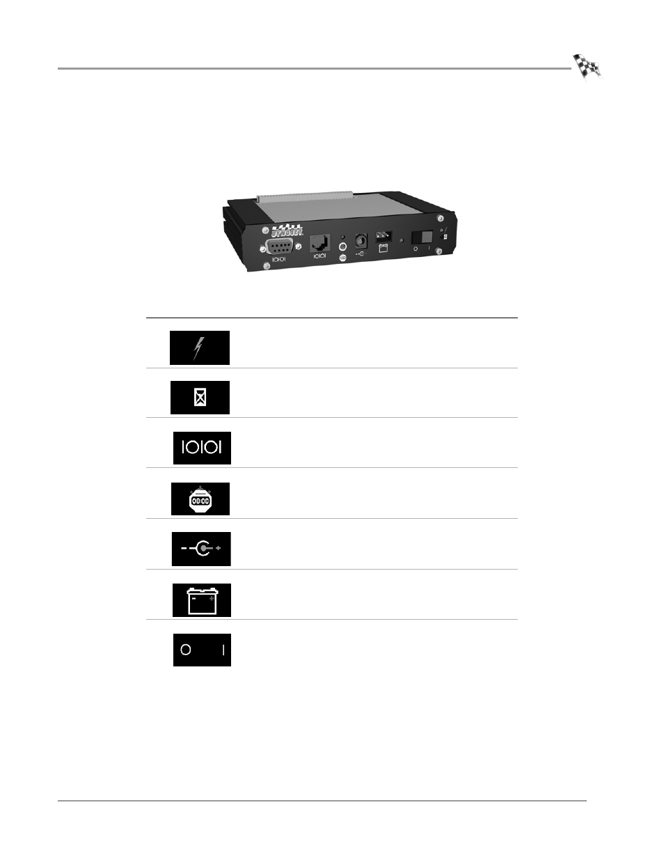
Figure 3-4: CPU Module
LED indicator
description
The green LED glows when the CPU module is receiving
power.
The blue LED is lighted when data from the modules is
being acquired and saved.
One of these connectors is used to communicate to the
main computer. The 9-pin connector (left) attaches to
the PC’s RS-232 serial communications port.
This connector provides a synchronization signal to a
third party data acquisition system.
This connector provides 12 volt DC power to a third
party data acquisition system.
This connector accepts 12 volt DC power from a power
supply or battery. The adjacent LED glows bright green
when power is properly connected.
When this switch is on, power is supplied to all
connected modules.