Dynojet 224/4WD: Installation Guide User Manual
Page 36
In Ground Model 224 4WD Automotive Dynamometer Installation Guide
C H A P T E R 2
Routing Cables
2-16
5
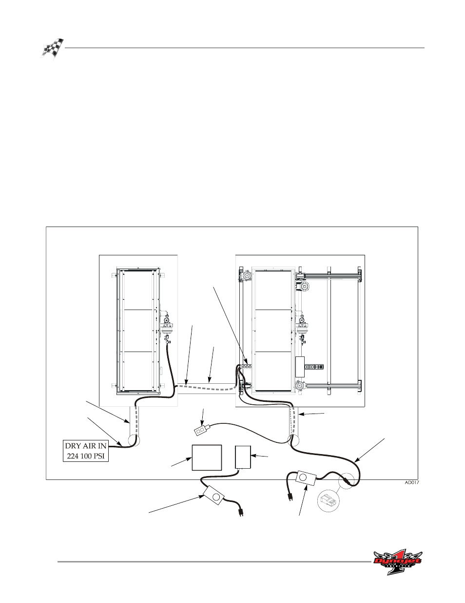
Route the air hose (F) from the cable track, through the conduit, and connect to
your clean, dry air supply at 100 psi.
Note: Verify the stationary dyno has clean dry air supplied to the air brake;
regulated to 100 psi for 224 stationary dynos and 60 psi for 248 stationary dynos.
The air brake comes installed with a hose barb for a 3/8-inch inside diameter air
hose. If your hose does not have an inside diameter of 3/8-inch then you will need
an air hose nipple (1/4-inch NPT) to connect your clean, dry shop air supply to
the dyno. Once the pressure is connected, the air brake is ready to use.
6
Route the power cable (D) from the cable track, through the conduit, and connect
to the power supply. Plug the power supply into your power source.
7
Connect the power supply to the dyno electronics. Plug the power supply into
your power source.
8
Route the dyno movement pendant cable (E) from the cable track, through the
conduit, and connect to the pendant.
Figure 2-13: Routing Cables Continued—224 224-4WD
pit
conduit
224 stationary dyno
224 4WD dyno
(D) power cable
pit conduit
computer
monitor
dyno
electronics
(E) dyno movement
pendant
cable track
(F) air
hose
(F) air
hose
power supply for
4WD dyno
power supply for dyno
electronics
pit conduit