Routing cables—224xlc – Dynojet 224/4WD: Installation Guide User Manual
Page 38
In Ground Model 224 4WD Automotive Dynamometer Installation Guide
C H A P T E R 2
Routing Cables—224xLC
2-18
. . . . . . . . . . . . . . . . . . . . . . . . . . . . . . . . . . .
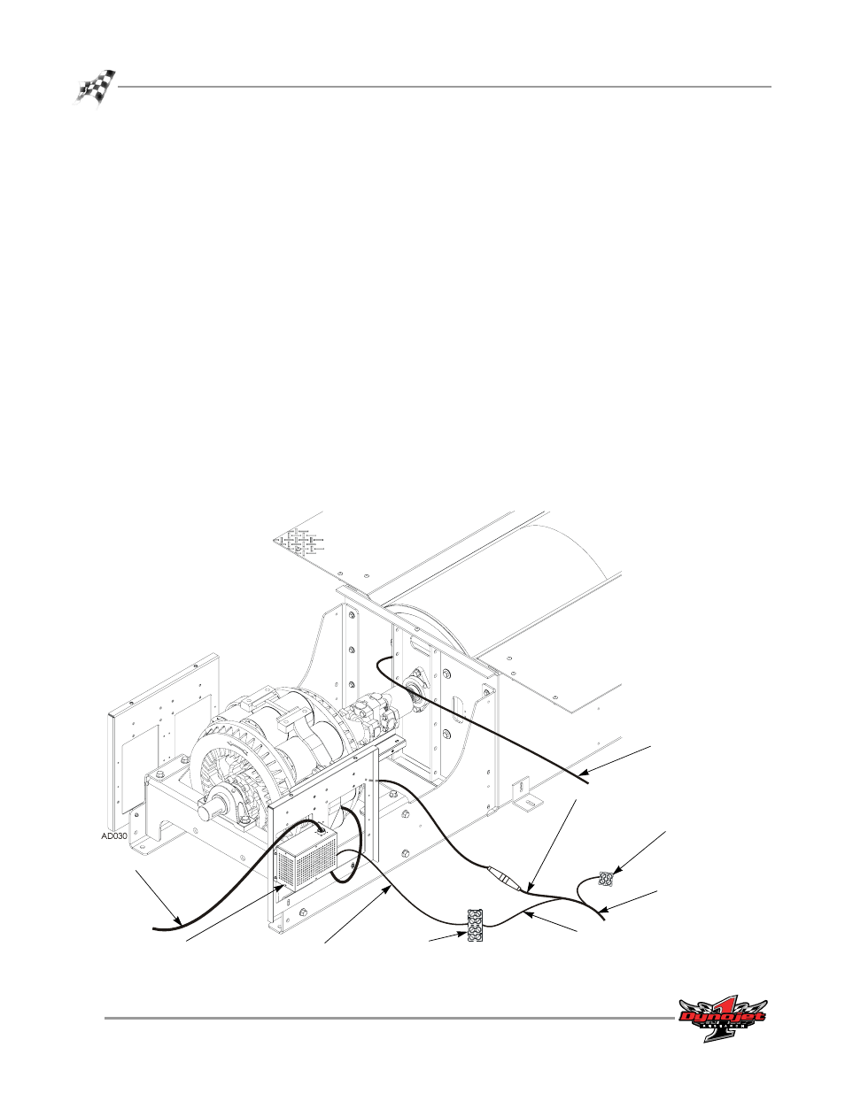
ROUTING CABLES—224XLC
Use the following instructions for routing cables when the 224 stationary dyno is
equipped with an eddy current brake.
1
Connect the temperature sensor cable from the eddy current brake to the
multi-purpose cable (C-3).
2
Connect the pickup card cable (B) to the pickup card.
3
Route the brake power cable from the eddy current brake through the pit cover
support and over to the Theta Controller (underneath).
4
Route the input power cable from the Theta Controller through pit cover
support, through the PVC conduit in the pit (not used by any other cables), and to
your power source.
Refer to the Eddy Current Brake Installation and User Guide for Model 224 Pit
Automotive Dynamometers (P/N 98215101) for more information.
5
Locate the four position terminal strip.
6
Connect the control cable from the Theta Controller to the terminal strip as
shown in Figure 2-16 on page 2-19.
7
Connect the load control cable (C-2) to the terminal strip as shown in Figure 2-16
on page 2-19.
Figure 2-15: Routing Cables—224xLC
control cable
input power cable
theta controller
pickup cable
from 4WD dyno
(C) multi-purpose
cable from 4WD dyno
C-3 temperature
sensor cable
C-2 load control cable
terminal strip
C-1 brake power
cable connected to
brake solenoid