Installing the extension arm assembly – Dynojet 200: High Pressure Blower User Manual
Page 15
M O D E L 2 0 0 / 2 5 0 B L O W E R I N S T A L L A T I O N
Installation
Version 3
High Pressure Blower Installation Guide
A-3
I
NSTALLING
THE
E
XTENSION
A
RM
A
SSEMBLY
The blower extension arm assembly comes ready to mount to the tire stop on the
dyno.
Note: If you have a power carriage installed on your dyno, you will need to make
adjustments to the extension arm assembly before mounting the assembly to the
dyno. Refer to “Modifying the Extension Arm Assembly (For Power Carriage
Only)” on page A-6.
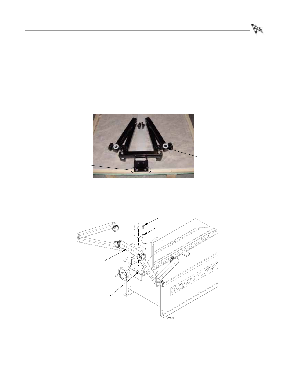
1
Remove the two screws securing the extension arm assembly to the crate and
remove the assembly.
Figure A-2: Remove the Extension Arm Assembly from the Crate
2
Secure the main bracket on the extension arm assembly to the tire stop using four
3/8-16 x 1.5-inch bolts and four 3/8-inch washers.
Note: If you modified the tire stop, you will also need to use four 3/8-inch nylock
nuts.
Figure A-3: Secure the Extension Arm Assembly to the Tire Stop
remove screws
clip zip tie securing poly washer
before installing blower
bolt
washer
main bracket
tire stop