Dynojet 188R: Eddy Current Brake User Manual
Page 18
16
Document #98232100
Step 3
Use a 3/8” nut to secure a wire loop to the frame
bolt. Run the wire from the Control Box through the
wire loop and then through the grommet in the
frame. Leave the nut loose, you will run another
wire through the loop later.
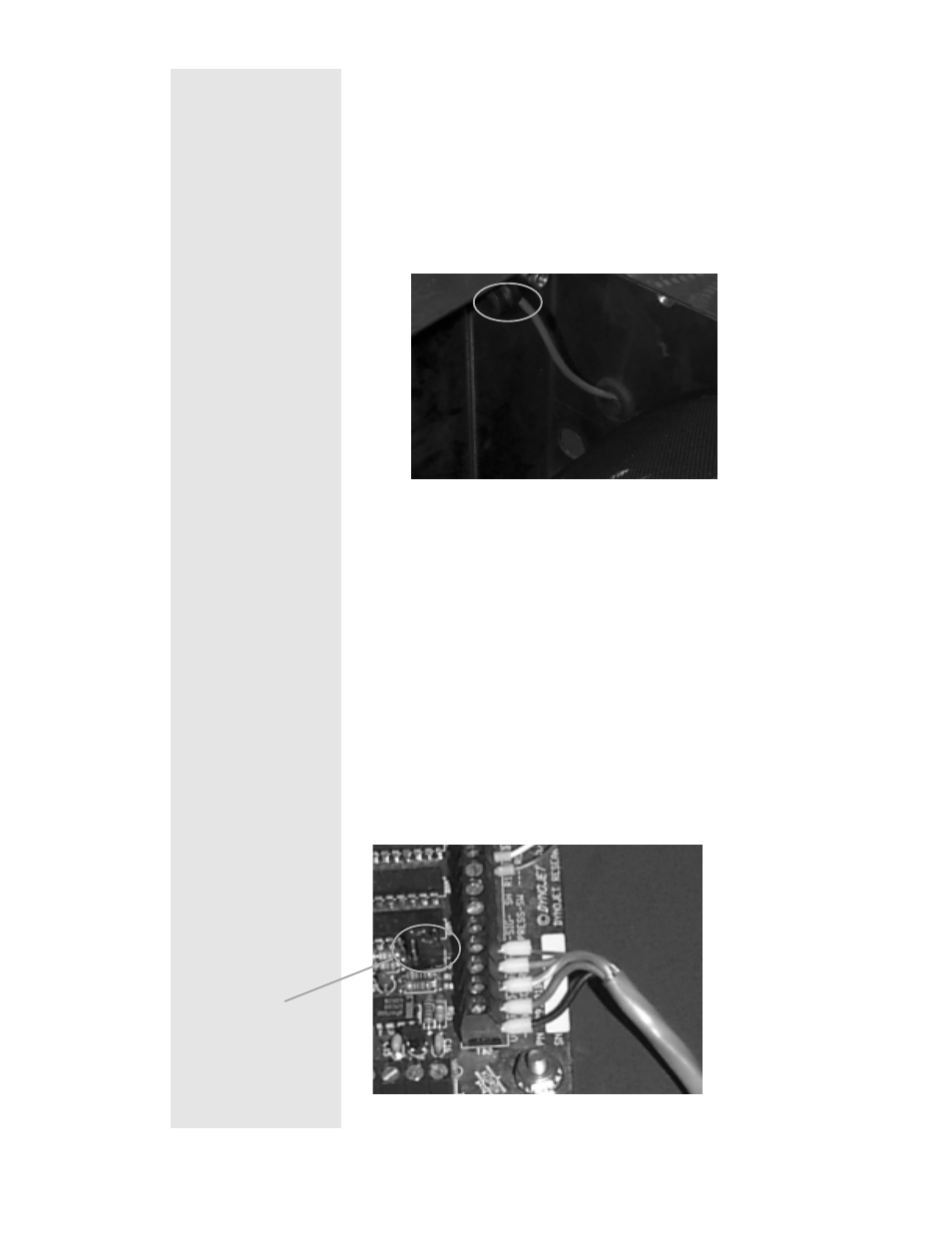
Step 4
Wire the Control Cable from the Control box to the
Breakout board.
- The control cable has 5 wires. They connect to
the wiring block on right side of the breakout
board labeled
“ -LOAD CONTROL - “.
The black wire connects to V-.
The red wire connects to V+.
The clear wire connects to O+.
The green wire connects to O-.
The ground wire connects to SH.
See picture below.
Jumpers
This manual is related to the following products: