1 serial port cable diagram – DSS Networks 8261-RTM User Manual
Page 22
Gigabit Ethernet Metro-Switch
Board and Firmware Users Manual
DSS NETWORKS, INC.
Version: 1.14g
Page: 22
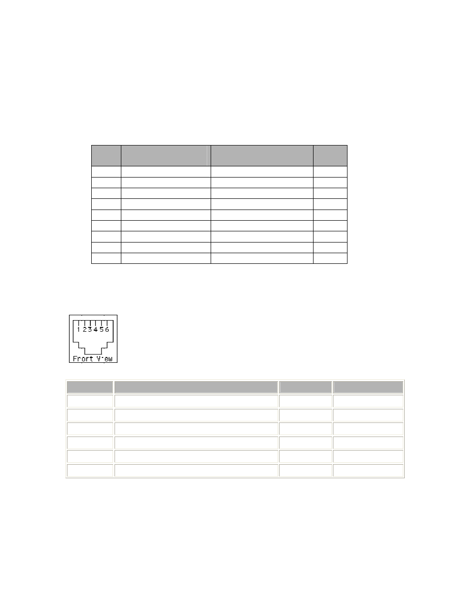
7.1 SERIAL PORT CABLE DIAGRAM
Included in each Metro-Switch kit shipped from the factory to the customer is one RJ-11
male to DB9 female RS232 serial port cable for connecting to the PC’s serial COM port
for use with a terminal emulator in a PC. The following table shows the cabling diagram
for this serial port cable:
RJ11
Pin
RS232 Signal
COM PORT Signal
DB9
Pin
1
Not used
Not used
1
2
Transmit Data (TD)
Receive Data (RD)
2
3 Ground
Ground
5
4
Not used
Not used
4
5
Receive Data (RD)
Transmit Data (TD)
3
6
Not used
Ground 6
N/A
Not used
Not used
7
N/A
Not used
Not used
8
N/A
Not used
Not used
9
RS-232 Signals on an RJ11 Jack
RJ11 Wire Signal
DTE
DCE
1
hardware flow control transmit (optional) RTS or DTR CTS and/or DSR
2 transmit
3 transmit
ground
4 receive
ground
5 receive
6
hardware flow control receive (optional) CTS or DSR RTS and/or DTR