Power consumption specifications, Hardware installation – DSS Networks 8261-RTM User Manual
Page 20
Gigabit Ethernet Metro-Switch
Board and Firmware Users Manual
DSS NETWORKS, INC.
Version: 1.14g
Page: 20
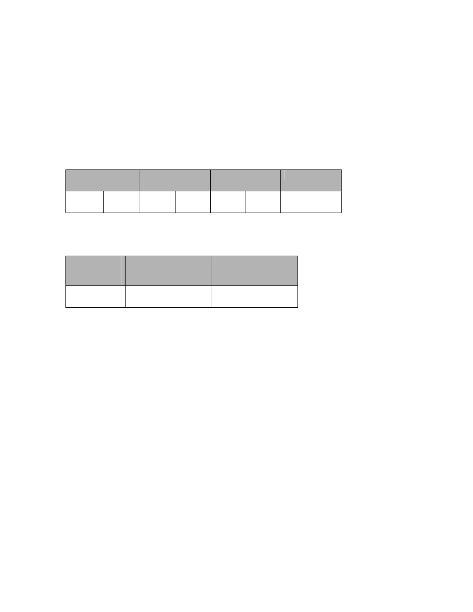
6. POWER CONSUMPTION SPECIFICATIONS
All board power is derived from 5V power rail to CPCI “J1” connector.
Note: The 3.3V onboard power has its own power regulator taken from the 5V rail,
however it can optionally be jumpered to use the 3.3V power rail from the J1 CPCI
connector.
Onboard power supplies
1.2V Power
(mA, A)
2.5V Power
(mA, A)
3.3V Power
(mA, A)
Power (W)
6.584A
7.91W
3.01A
7.53W
1.025
3.39W
18.83W
J1 CPCI Connector Power Rails
3.3V Source
Current (mA,
A)
5V Source (main
supply)
Current (mA, A)
12V power rail
Not used ***
5A (max)
Not used
*** Note: Board can be optionally jumpered at factory to use 3.3V onboard from
3.3V power rail for power distribution.
7. HARDWARE INSTALLATION
Before attempting to install the Metro-Switch into your system, please make sure to
check and verify the following:
Shut off the power to the system and chassis and any peripherals. It is important to
remove the power cable to the system chassis.
Step 1: Assess system power requirements. If you already have other CPCI cards in
your system, make sure that your system is able to provide the necessary power to
support the addition of the Metro-Switch fabric card. Check your systems user manual
for power specifications and limitations.
Step 2: Ground yourself. Many electronic components inside computer and on the
Metro-Switch can be severely damaged by receiving a shock of static electricity. Before
touching any electronic components or boards, discharge any static electricity on your