B&M 70441 HOLESHOT 2400 User Manual
Page 3
3
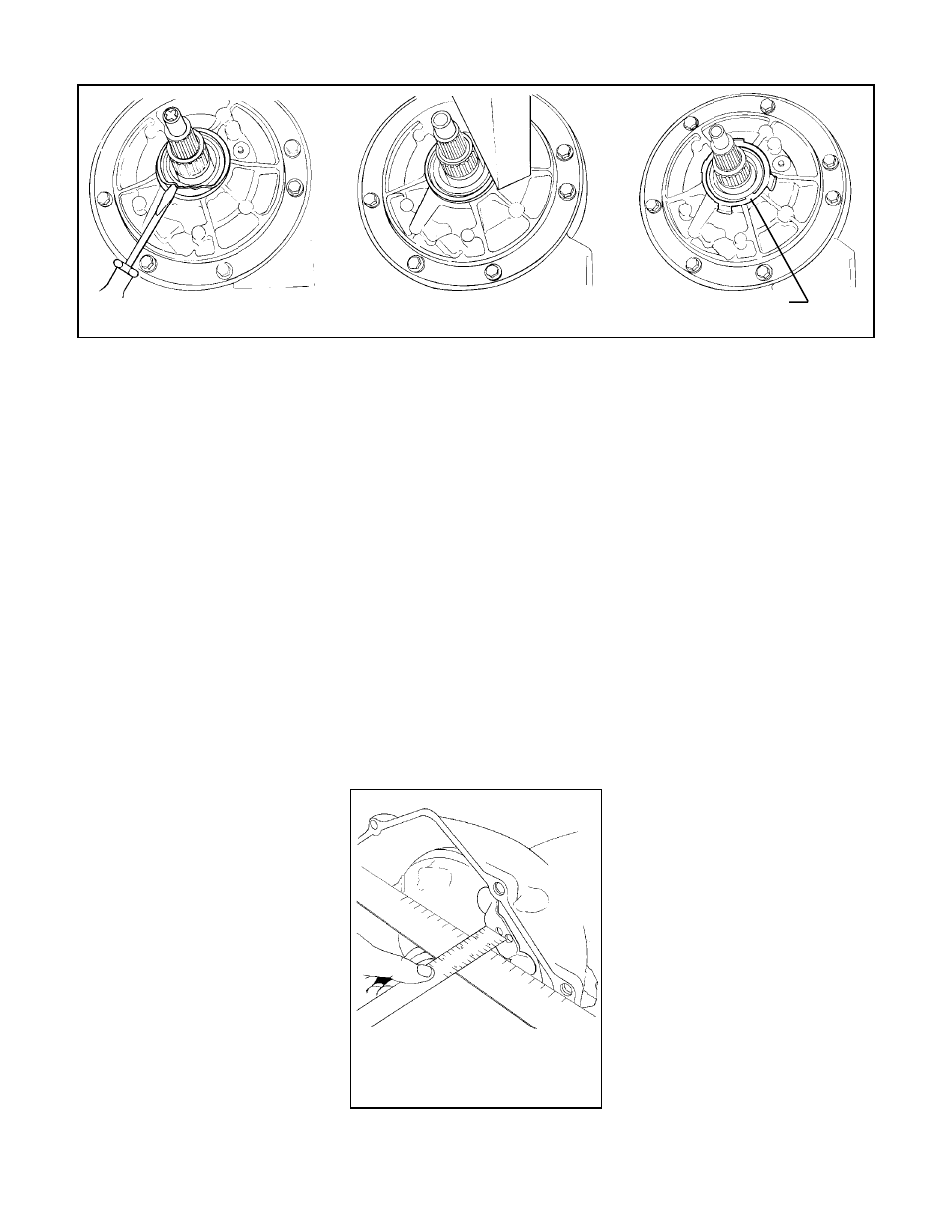
Fig. 5
Drive lug face must be at least 1"
inside front edge of bellhousing
Locate seal retainer tab
at 5 O'clock position
input shaft, reaction shaft and pump
drive tangs. Place a straight edge across
the bellhousing face and measure the
distance to the torque converter’s drive
lug face. The drive lug must be at least 1"
inside the bellhousing, see (Fig. 5). A
measurement of less than 1" indicates
the torque converter is not fully engaged
in the transmission. Continue to push in
and rotate the converter until you obtain
full engagement. If you install the trans-
mission without full converter engage-
ment, you will damage the oil pump.
STEP 15. Place the transmission in po-
sition on transmission jack. Make sure
the jack supports the transmission on a
wide area so the oil pan is not crushed.
Install the transmission / converter
against the engine. The transmission
should engage the dowel pins and sit flat
against the block with hand pressure
only. If the transmission does not sit flat
against the engine, the converter is not
fully engaged in the transmission or
some other interference problem exists.
Do not attempt to pull the transmission
up to the engine with the bellhousing
bolts as this can cause transmission or
torque converter damage.
STEP 16. Once the transmission is in
position against the engine, install the
bellhousing bolts and torque to 35 lb.ft. At
this point the torque converter should
turn freely. A tight converter indicates
improper engagement, distorted
flexplate or binding pilot hub. This condi-
tion must be corrected before going
any further.
STEP 17. Inspect transmission mount.
Worn, cracked or broken transmission
and/or engine mounts should be re-
placed. Raise transmission and install
crossmember assembly then tighten all
bolts. Install three (M10 x 1.5) flexplate to
converter bolts. Install the first bolt finger
tight then use the starter motor to “bump”
each drive lug into position. When all
three bolts are installed torque them to
47 Nm (35 lb.ft.).
STEP 18. Remove the oil pan and filter.
The filter suction tube O-ring may stick in
the pump body, if it does make sure to get
it out. Assemble two (2) O-rings on a new
oil filter. Some filters have a
preassembled seal on the suction tube,
if the filter you are using has a
preassembled seal do not use the O-
rings. Lubricate the suction tube seal
with clean transmission fluid and install
filter into the transmission.
STEP 19. Remove all old gasket mate-
rial from the pan and case flange. Install
a new pan gasket then assemble pan to
the transmission. Install ALL of the pan
bolts (install shifter cable bracket if
equipped) finger tight first then torque to
8 lb.ft. DO NOT use a sealant on the pan
gasket and don’t over torque the pan
bolts, this will damage the gasket and
cuase the pan to leak transmission fluid.
STEP 20. If your transmission is
Pump seal removal and installation
Fig. 4
alloy and can be easily damaged during
seal removal. We recommend the fol-
lowing seal removal procedure to mini-
mize the chance of damaging the pump
housing, see (Fig. 4).
1. Raise the transmission (or place on
bench) so that the seal is accessible
from the lower side of the transmission.
2. Using a common (flat) screwdriver
collapse the seals outer flange as
shown. Be careful not to damage the
housing with the screwdriver.
3. With the outer flange collapsed the
seal should pry out easily. Again take
care not to damage or gouge the hous-
ing. Once the seal is removed use a lint
free rag wrapped around a thin piece of
wood or other soft material, (to avoid
scratching the seal bore) to clean the
seal bore thoroughly.
STEP 11. Coat the outer diameter of the
new oil seal with “Locktite, 609” or
“Permatex, Secures Gears” cylindrical
retaining compound. Then using a small
block of wood between the seal and
hammer, carefully tap the seal evenly
into the housing until fully seated. If the
transmission was equipped with a seal
retainer, install the retainer onto the
housing as shown, see (Fig. 4).
STEP 12. Hold your B&M torque con-
verter against the crankshaft and
flexplate to check the pilot hub fit. The
converter pilot hub should fit in the crank-
shaft snugly with no excessive slop. A
tight fit indicates burrs or debris in the
crankshaft pilot diameter. The burrs or
debris can be removed with sand paper.
STEP 13. Pour 1 quart of transmission
Fluid into the B&M torque converter so
there will be some lubrication on initial
startup. Lubricate the converter’s pump
drive hub with clean transmission fluid.
STEP 14. Install the B&M torque con-
verter onto the transmission. Push the
converter in while rotating it to engage the
- 70440 Torque Converter, Holeshot 2000 GM 4L60E 1997 to 2003 Corvette, Camaro and Firebird with LS1 Engin 70422 Torque Converter, Traveler Converter GM TH700R4 1993 to 1996 30 Spline, 1984 to 1993 4L60E 30 Spline 70420 TORK MASTER 2000 30 SPLINE W/CLUTCH 70419 Torque Converter, Holeshot 2400 70417 HOLESHOT 2000 30 SPLINE W/CLUTCH 70415 TORQUE CONVERTER, HOLESHOT 2400