2fig. 2 fig. 3 – B&M 70441 HOLESHOT 2400 User Manual
Page 2
2
Fig. 2
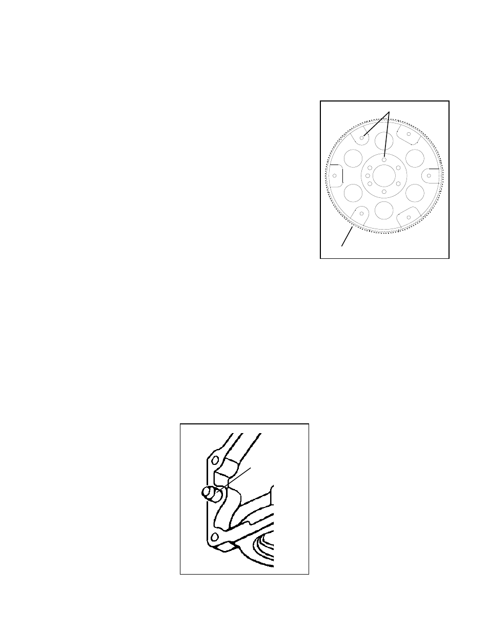
Fig. 3
Inspect bolt holes
tion by using the B&M Converter Lockup
Control (#70244 for mechanical drive
speedometers, #70248 for GM elec-
tronic speed sensor applications).
These torque converters can be
used on the GM 4L60E electronically
controlled transmission used on 1993 -
96 Chevrolet and GMC trucks and 1994-
97 Camaros and Firebirds. On later
model vehicles equipped with an LS1
type engine, the input shaft is longer and
can only use the 70440 and 70441 con-
verters. For this transmission (4L60E)
you must not make any electrical con-
nection changes. Using it as a non
lockup unit will cause error codes to be
generated and the "Check Engine" light
will be illuminated.
TRANSMISSION REMOVAL
The TH200C, TH200-4R, TH700-R4 and
4L60E are METRIC dimensioned and
have METRIC fasteners.
Because of variations between differ-
ent vehicle models we cannot cover each
in detail. Instead we will outline a basic
removal and installation procedure. The
sequence of the following procedures
may have to be changed to suit different
vehicle installations. We recommend
you change the transmission fluid and
filter when installing your B&M torque
converter.
Automatic transmissions normally
operate between 150 F and 250 F. It is
recommended that the transmission be
allowed to cool thoroughly to avoid burns
from hot oil and parts. The vehicle must
be off the ground for ease of transmis-
sion removal. A vehicle hoist is best,
however jack stands or wheel ramps will
work fine. MAKE SURE THE VEHICLE IS
FIRMLY AND SECURELY SUPPORTED!! A
transmission jack should be used to
prevent personal injury and or transmis-
sion damage during removal and instal-
lation. Have a small box handy to put nuts
and bolts in so they don’t get lost. A drain
pan to catch oil is also required.
STEP 1. Place drain pan under the
transmission to catch the oil. Drain the oil
pan by first removing the front bolts then
working from the front loosen all the
remaining pan bolts. If the pan sticks use
a screwdriver to pry the pan loose. Again
working from front to rear allow the pan to
tilt down in the front and drain as the
remaining bolts are removed. Once
drained replace the oil pan and hold in
place with one bolt at each corner. To
avoid all this mess next time you service
your transmission, you may want to con-
sider installing a B&M Drain Plug Kit,
#80250 while the oil pan is off the trans-
mission.
STEP 2. Remove the driveshaft (and
torque arm if equipped) being careful not
to drop the U-joint bearings. It’s a good
idea to tape the bearings in place and
wrap the smooth seal diameter of the
slip yoke to prevent damage. It may be
necessary to remove or disconnect any
exhaust pipes and/or hangers during
transmission removal. Remove transfer
case if equipped.
STEP 3. Disconnect the cooler lines.
Use a fitting wrench to avoid damaging
the tube compression nuts. Some mod-
els are equipped with a T.V. cable that
runs from the transmission up to the
throttle linkage on the engine. Discon-
nect the T.V. cable at the engine end and
feed the cable down so it hangs freely
from the transmission. Disconnect any
electrical connectors from the sides of
the case. Be sure to note or label the
position of each corresponding connec-
tor. Disconnect the transmission shifter
cable from the shift lever. Disconnect the
speedometer cable or electrical Vehicle
Speed Sensor connector at rear of trans-
mission.
STEP 4. Remove the bell housing dust
cover to expose the torque converter.
Remove the three converter bolts. The
converter should now rotate freely. If it
does not pry the converter back slightly
and free it from the crankshaft.
STEP 5. Place transmission jack under
transmission and take the load off the
crossmember. If the vehicle is equipped
with a rear mounted distributor on the
engine, it is advisable at this point to
remove the distributor cap so it will not be
damaged as the transmission is low-
ered. Remove the crossmember as-
sembly.
STEP 6. Remove the bellhousing
bolts, it may be necessary to lower the
transmission slightly to gain clear ac-
cess to the bolts. Finish lowering the
transmission until engine is balanced
on it’s mounts then pull the transmission
Inspect ring gear teeth
slightly away from the engine. Make sure
the converter stays with the transmis-
sion and does not fall out. It may be
necessary to remove the dipstick tube at
this point to continue lowering the trans-
mission. Remove transmission and
converter assembly from vehicle.
With the transmission completely out
of the vehicle the torque converter can
easily be removed by pulling it straight off
the front. Drain the torque converter as
completely as possible then cover the
hub to keep out dirt.
STEP 7. Inspect the engine block’s
transmission mounting face to be free of
any dirt or burrs. Make sure both dowel
pins are installed and stick out of the
block at least 1/2" to insure proper trans-
mission alignment, see (Fig. 2).
STEP 8. Remove and inspect the
flexplate for distortion, cracks or dam-
aged ring gear teeth, see (Fig. 3). If the
flexplate shows any damage it should be
replaced. Do not attempt to repair a dam-
aged flexplate.
STEP 9. Assemble the flexplate to
crankshaft and align all holes before
installing the bolts. When properly in-
stalled the raised inner lip on the
flexplate should face away from the
crankshaft flange. Torque the bolts to 60
ft.lbs.
STEP 10. Carefully remove the front seal
from the oil pump housing. CAUTION:
The oil pump housing used in these
transmissions is made of an aluminum
Dowel pin must
protrude 1/2" for
proper transmis-
sion engagement
- 70440 Torque Converter, Holeshot 2000 GM 4L60E 1997 to 2003 Corvette, Camaro and Firebird with LS1 Engin 70422 Torque Converter, Traveler Converter GM TH700R4 1993 to 1996 30 Spline, 1984 to 1993 4L60E 30 Spline 70420 TORK MASTER 2000 30 SPLINE W/CLUTCH 70419 Torque Converter, Holeshot 2400 70417 HOLESHOT 2000 30 SPLINE W/CLUTCH 70415 TORQUE CONVERTER, HOLESHOT 2400