Taylor-Wharton XL-55HP (with dual regulators) User Manual
Page 6
inner container is vaporized in a heat exchanger which is inside
the outer casing. The expanding gas is fed into the upper sec-
tion of the container to build pressure. The resulting process will
drive either the liquid or gas delivery system.
Pressure Building is not normally required unless container pres-
sure drops below the gas output pressure desired. If, for ex-
ample, the container pressure gauge reads 250 psig (17.2 bar/
1724 kPa), and your gas pressure requirement is 270 psig (19
bar/1860 kPa), and the pressure building valve may be opened
to build container pressure to 300 psig (20.7 bar/2068 kPa).
Economizer An economizer circuit withdraws gas preferen-
tially from the head space over the liquid container gas that
would otherwise be lost to venting. Excess pressure in the head
space of the container is relieved by allowing gas to flow from
this area directly to the USE valve outlets while gas is being
withdrawn from the container; yet normal operating pressure is
preserved to ensure uninterrupted product delivery. The econo-
mizer is automatic and requires no operator attention.
The USE Valve This valve controls the gas outlet that allows
product withdrawal through the internal vaporizer. It has the re-
quired CGA connection that matches the gas service for which
the container is configured.
The LIQUID Valve Liquid product is added or withdrawn from the container through the
connection controlled by this valve. It has the CGA fitting that is required for liquid line
connections. The valve is opened for fill or liquid withdrawal after connecting a transfer
hose with compatible fittings to the LIQUID line connection.
RELIEF VALVES AND RECOMMENDED REGULATOR SETTINGS
Relief
Pressure
Normal
Valve
Building
Economizer
Operating
Setting
Setting
Setting
Range
22 psig
N/A
N/A
0-22 psig
1.5 bar
N/A
N/A
0-1.5 bar
152 kPa
N/A
N/A
0-152 kPa
230 psig
125 psig
145 psig
75-175 psig
16 bar
8.6 bar
10 bar
5-12 bar
1586 kPa
862 kPa
1000 kPa
517-1207 kPa
350 psig
300 psig
320 psig
200-350 psig
24 bar
20.7 bar
22 bar
13.8-24 kPa
2413 kPa
2068 kPa
2206 kPa
1379-2413 kPa
500 psig
400 psig
420 psig
300-600 psig
34 bar
28 bar
29 bar
20.7-41 bar
3447 kPa
2758 kPa
2896 kPa
2068-4137 kPa
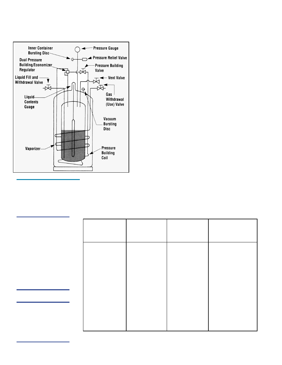
XL-45HP/XL-50HP/
XL-55HP and XL-
50VHP Flow
Diagram
NOTE:
The economizer and
pressure building
functions are controlled
by a single dual action
regulator. The pressure
delta between the
pressure building
setpoint and the
economizer setpoint is
approximately 20 psig
(1.4 bar/138 kPa). This
delta cannot be altered.
WARNING:
Never use the Dual
Pressure Building/
Economizer Regulator
or Relief Valve for the
XL-50VHP on any other
container.
6