Taylor-Wharton XL-55HP (with dual regulators) User Manual
Page 21
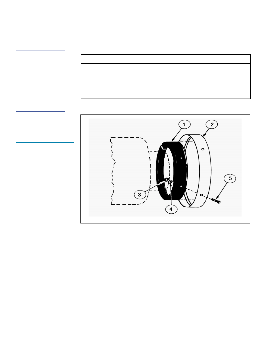
SHOCK MOUNT FOOT RING
Item No.
Description
Part No.
(XL-55 Only)
Qty.
1
Rubber Shock Ring
XL50-4C18
(GL55-4C21)1
2
Foot Ring
XL50-4C19
(GL55-4C19)1
3
Hex Nut
6310-0135
4
4
Washer
6430-0125
4
5
Carriage Bolt
6620-0401
4
Replacement of Shock Mount Foot Ring
1. Empty or transfer all contents of tank. Vent to atmospheric pressure.
4
2. Gently lay the container on its side and unbolt the four (4) carriage bolts that attach the
foot ring and rubber shock ring to the tank.
3. Slide off the damaged foot ring and rubber shock ring.
4. Assemble rubber shock ring into new foot ring and force over shock mount ring on
container. Use a rubber hammer to drive the rubber shock ring back into place.
5. Using a ½ in. drill but, drill holes through the rubber so that the carriage bolt slides in
smoothly.
6. The holes in foot ring must be positioned in alignment with holes in shock mount ring.
Using the 4 bolts, washers and nuts, fasten the new parts of the container.
7. After securing the shock mount ring, gently life the container to the upright position
and inspect your work.
NOTE:
If the original Shock
Mount Ring is badly
damaged we
recommend that an
NER test is performed
to ensure that no
internal damage has
resulted from the
impact of the shock
mount ring.
4
For containers in C0
2
service, see caution on releasing container pressure at the beginning of the
Maintenance section.
Shock Mount Foot
Ring - Exploded
View
21