Full view contents gauge maintenance – Taylor-Wharton XL-55HP (with dual regulators) User Manual
Page 16
FULL VIEW CONTENTS GAUGE MAINTENANCE
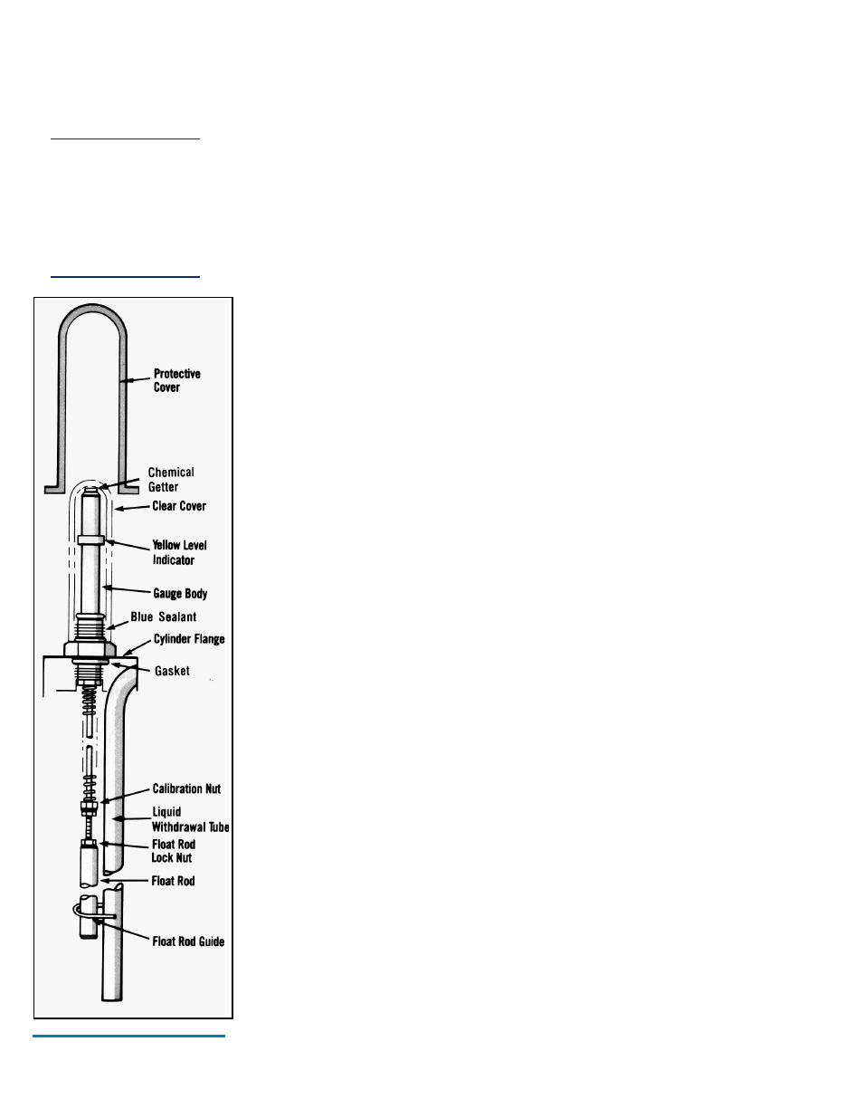
The content of these containers is measured with the Full View Contents Gauge. The
device consists of the gauge assembly beneath a clear plastic protective cover. When the
gauge is assembled, a level indicator ring is magnetically coupled to the top of a float rod
and moves up or down with the changing level of liquid in the container. The clear cover
over the gauge body and level indicator is sealed at assembly to resist fogging of the
gauge. This seal should never need to be broken.
Removing the Full View Contents Gauge
1. Vent all pressure from the container.
3
2. Remove the protective cover by removing three bolts from the base of the cover.
3. Unscrew the gauge body using a wrench on hex fitting as base of the indicator.
4. Life the entire gauge assembly free of the container. The gauge assembly is long and
may be very cold. Gloves should be used to protect your skin.
Calibration Procedure for Liquid Level Contents Gauges
1. You will need a column of water approximately 4 ft. (1.2 m) tall. A clear plastic tube 2.0
in. (51 mm) dia. with a cap glued to one end is perfect. Place an oxygen service
contents scale sleeve (P/N GL50-9C43) over the sight tube.
2. Support the gauge assembly by holding the base of the indicator tube. Care must be
taken to prevent interference with the spring action or from misaligning the scale sleeve.
Immerse the aluminum float rod below the water level as illustrated. The gauge assem-
bly must be held vertically and the rod must not touch the side or bottom of the tube.
The yellow level indicator of the gauge should indicate a full level reading with the
oxygen scale.
If the gauge fails to indicate a full liquid level, the assembly is to be removed from the
water, calibrated and retested.
To change calibration, loosen locking nut away from brass calibration nut and turn the
threaded rod with respect to the calibration nut.
If the rod is turned clockwise (to the left) with respect to calibration nut, the exposed
portion of rod becomes longer and the gauge yellow band will be lowered.
To raise the yellow band, turn rod counterclockwise. The exposed portion of rod becomes
shorter. Once you have adjusted calibration, recheck for proper setting. (See illustration.)
After proper setting has been obtained, lock down nut against calibration nut.
3. Once the gauge assembly has been calibrated to read full in water, it must be verified that
it reads empty when the aluminum float rod is suspended in the air. The yellow indicator
must be as close to the bottom as possible (inner rod will be firmly bottomed out).
If calibration is required to make the gauge read empty in air, it must be rechecked in
water.
4. After calibration, you will need to follow contents gauge installation to reinsert gauge.
Be sure to dry the assembly before reinserting into the cylinder to prevent ice build-up
that could restrict movement to catch on the guide ring inside the cylinder.
3
For containers in C0
2
service, see caution on releasing container pressure at the beginning of the
Maintenance section.
WARNING:
Cold surfaces should
never be handled
with bare skin. Use
gloves and other
protective clothing
when performing this
procedure.
Full View Contents
Gauge
16