Taylor-Wharton KRYOS Controller User Manual
Page 10
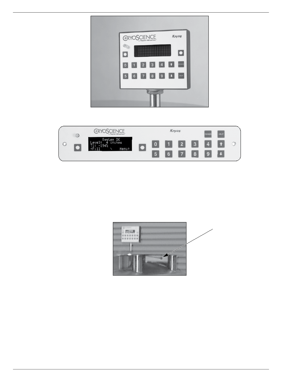
Figure 2.0 KRYOS Interface Panel for LABS units and K-Series unit 38K
Figure 2.1 KRYOS Interface Panel for K-Series units 10K and 24K
Main Control
The “brain” for the control system “talks” to the interface unit and makes all
decisions regarding liquid levels, temperatures, valve opening/closing, etc. On the
LABS Series it is located on the upper outer head. (See Figure 3.0) On the 10K and
24K it is located inside the front cabinet. On the 38K it is located at the rear of the
unit.
Main Control
Figure 3.0 KRYOS Main Control for LABS
Sensor Assembly
A standard 7 thermistor assembly, includes the Freeze-Guard sensor located after
the solenoid valve in the plumbing assembly. In the unlikely event that the solenoid
valve does not close when the liquid nitrogen reaches the stop fill sensor then an
action is triggered to close the valve. If it does not close an alarm is triggered.
Optional 4-thermistor, or 8-thermistor sensor assemblies can be ordered. The
4-thermistor assembly maintains the liquid level between 2 middle sensors. The
8-thermistor assembly maintains the liquid level between the high sensor and the
low sensor assigned by the user.
KRYOS
8