Warning, Caution, Fig. 1 – Qmark QTS - Toe Space Fan-Forced Heaters User Manual
Page 2
NOTE:
Heater should be controlled by either built-in thermostat
or wall thermostat. Either is purchased separately. A wall ther-
mostat requires a separate feed from heater to thermostat.
NOTE
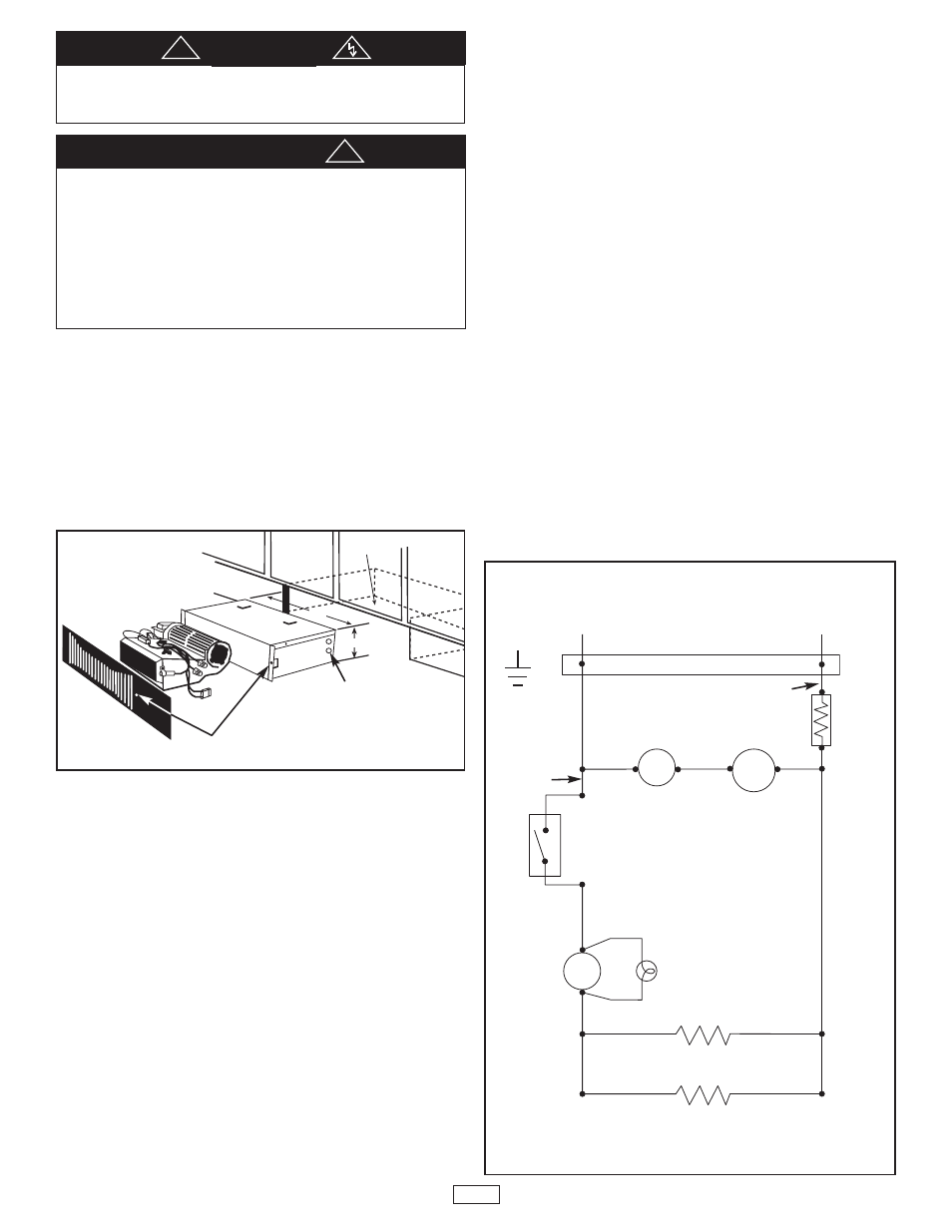
: Hole location should be 12” from corner and 1/4” above fin-
ished floor.
HORIZONTAl INSTAllATION ONly
This heater may be wired with standard building wiring (rated
minimum 60° C).
1. Cut
a 14 1/4” x 3 5/8” (361.9 x 92.1 mm) opening at desired
location as shown in Fig. 1. Keep clearance area free of
obstructions.
2. Remove top cover from heater enclosure by removing the
cover screws.
3. Determine which knockout in enclosure will be used for field
wiring and remove (see figure 1). Install strain relief (field sup-
plied).
4. Fish field wiring through strain relief leaving 6” (12.7 mm) of
wire inside box.
5 FOR BUILT-IN THERMOSTAT, WIRE HEATER AS SHOWN
IN FIG. 2. Run field wiring from circuit breaker box to heater.
Connect to the two black pigtail leads for 240/208V model or
to black and white pigtail lead for 120V model with wirenuts
(provided). Remove the wirenuts securing two blue leads.
Connect the blue leads with wirenuts (provided) to thermostat
lead wires.
6. FOR REMOTE 2 POLE WALL THERMOSTAT, WIRE
HEATER AS SHOWN IN FIG.3. Run field wiring from circuit
breaker box to wall thermostat. Connect blue lead A with
heater to field supply lead from load side of thermostat.
Connect supply field wiring from thermostat to two black pig-
tail leads for 240/208V model or to black and white pigtail
leads for 120V model with wirenuts (provided). Connect field
ground lead to ground pigtail with wirenut (provided).
NOTE:
Whether it is with built-in thermostat or with remote ther-
mostat, there should always be a fan delay
ON
and a fan delay
Off
.
7. Replace and secure top cover on heater enclosure, and then
position heater into opening.
8. Using the holes in the flanges of the enclosure for a template,
secure both the front grille and the heater by drilling two .093”
(3/32”)(2.3 mm) diameter holes into the cabinet board and
installing two No. 6 x 3/4” (No.6 x 19 mm) screws (supplied).
When SAG adapter grille is used, the unit is attached to the
cabinet board thru the two outermost holes on the adapter
grille.
TO REDUCE RISK OF FIRE OR ELECTRICAL SHOCK,
DO NOT
INSTALL WITHOUT BACK BOX.
DO NOT
OPERATE WITHOUT
GRILLE INSTALLED.
WARNING
2
1.
DO NOT
USE HEATER FOR DRY OUT. PAINT, PLASTER, SAW-
DUST, AND DRYWALL SANDING DUST MUST BE KEPT OUT OF
HEATER.
2. THE HEATER IS HOT WHEN IN USE.
DO NOT
INSTALL
THE HEATER BEHIND DOOR, BEHIND TOWEL RACK, IN CLOSET,
WHERE CURTAINS OR DRAPES COULD TOUCH OR BECOME
SCORCHED BY HEATER, OR WHERE AIRFLOW TO HEATER MAY
BE OBSTRUCTED. KEEP ELECTRICAL CORDS, BEDDING, FURNI-
TURE AND OTHER COMBUSTIBLES AWAY FROM HEATER.
CAUTION
!
!
14-1/4
3-5/8
CLEARANCE AREA
FOR HEATER
CABINET
Fig. 1
Hole “A”
Knockouts
L1
GND
L2 or N
SOCKET PLUG
Black
Blue
Blue
B
lu
e
Thermal
Fuse
Built-in Single Pole
Thermostat
(Or Remote Thermostat)
R
e
d
J
u
m
p
e
r
Rear Coil Element
Front Coil Element
Fan
Delay
Motor
Auto
Reset
Limit
Light
240V-Black
120V-White
Fig. 2 Wiring With Internal Heater Mounted
Thermostat
Wiring Diagram - Toe Space Heater
For lower wattage rating, remove red jumper