Warning, Fig. 6a, Fig. 6b – Qmark QFG Series - Electric Fan-Forced Wall Heaters User Manual
Page 3: Figure 7, Table 1, 208 volt model only, Figure 4
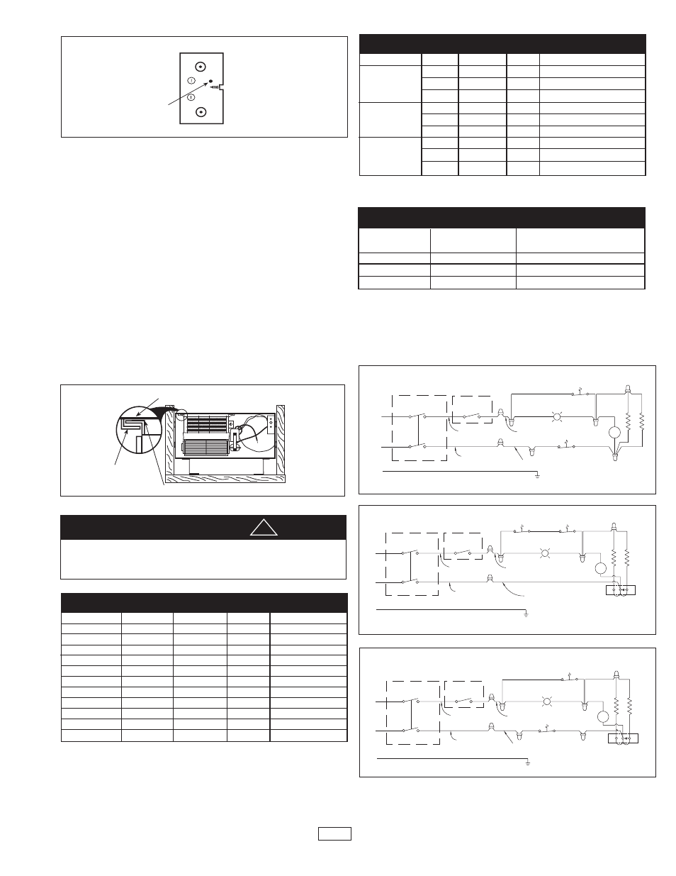
TO INSTALL FAN DECK ASSEMBLY
NOTE: Fan deck assembly should not be installed until after the
drywall phase of construction is complete. Dust from drywall
installation and joint compound can be harmful if it gets inside fan
deck components.
1.
Locate fan deck and mounting rails in top of back box.
2.
Insert flanges on fan deck into mounting rails and slide back until fan
deck stops (see Fig. 7).
3.
Referring to Table 1, determine the wiring diagram for the specific
model heater shown on heater nameplate. Make wiring connections
using appropriate wiring connectors. Connect ground to green col-
ored heater ground wire.
4.
Remove 1/2” knockout from grille and install grille using two oval
head screws. Push thermostat knob on thermostat shaft.
5.
Reconnect power at main fuse or circuit breaker distribution panel.
TABLE 3
TOTAL
AMPS
0 thru 12
12.1 thru 16
16.1 thru 24
WIRE SIZE
(COPPER)
#14
#12
#10
CIRCUIT BREAKER
OR FUSE SIZE
15 Amps
20 Amps
30 Amps
TOP OF BACK BOX
FLANGE ON FAN DECK
MOUNTING RAIL
Figure 7
L2 OR N
L1
NOTE: TCO IS A PART
OF ELEMENT ASSY
REMOTE
OR OPTIONAL
2 POLE STAT
LIMIT
CONTROL
LAMP
TCO
R
MOTOR
M
REMOTE
1 POLE STAT
OR OPTIONAL
GND - GREEN
BLACK
RED
RED
BLACK
BLACK
BLACK - 208V
Fig. 6A
L2
L1
NOTE: TCO IS A PART
OF ELEMENT ASSY
M
MOTOR
CONTROL
LIMIT
LAMP
TCO
R
REMOTE, BUILT-IN
2 POLE STAT
OR OPTIONAL
1 POLE STAT
OR OPTIONAL
REMOTE
GND - GREEN
RED 240V
RED
BLACK
BLACK
RED
BLACK
3 1
2
RED
JUMPER
BLUE
JUMPER
FRONT
ELEMENT
BACK
ELEMENT
Fig. 6C
NOTE: See table 1 for proper wire diagram.
SUPPLY VOLTAGE MUST MATCH HEATER NAMEPLATE VOLTAGE.
CONNECTION TO ANY OTHER VOLTAGE COULD CREATE RISK OF
FIRE OR PERMANENTLY DAMAGE HEATER.
a
WARNING
!
TABLE 1
MODEL
*G1512IFMB
*G1512MB
*G1512T2MB
G2028IFB
G2228IFB
*G2024IFMB
*G2024T2MB
*G2024M B
*G2224IFMB
*G2224MB
*G2224T2MB
VOLTS
120
120
120
208
208
240/208
240/208
240/208
240/208
240/208
240/208
WATTS
1500
1500
1500
2000
2200
2000/1500
2000/1500
2000/1500
2250/1688
2250/1688
2250/1688
AMPS
12.5
12.5
12.5
9.6
10.0
8.3/7.2
8.3/7.2
8.3/7.2
9.4/8.1
9.4/8.1
9.4/8.1
DIAGRAM
FIG. 6B
FIG. 6B
FIG. 6B
FIG. 6A
FIG. 6A
FIG. 6C
FIG. 6C
FIG. 6C
FIG. 6C
FIG. 6C
FIG. 6C
Note: “IF” Inner Frame models must be used with RBB back box.
For installations over 7500 ft. above sea level we recommend to use heaters with wattages
under 1500 watts.
“T2” Models include 2 Pole thermostat.
“M” Multi-Watt units include “Clip ‘n’ Fit”® feature and RBB back box.
* These models are shipped for maximum wattage. Refer to Table 2 to obtain lower wattage
ratings.
TABLE 2
MODEL
G1512IFMB
G1512MB
G1512T2MB
G2024IFMB
G2024MB
G2024T2MB
G2224IFMB
G2224MB
G2224T2MB
VOLTS
120
120
120
240/208
240/208
240/208
240/208
240/208
240/208
WATTS
1125
750
375
1500 /1125
1000/750
500/375
1688/1266
1125/844
562/422
AMPS
9.4
6.3
3.1
6.3
4.2
2.1
7.0
4.7
2.3
*ACTION
Clip out blue jumper only
Clip out red jumper only
Clip out red & blue jumpers
Clip out blue jumper only
Clip out red jumper only
Clip out red & blue jumpers
Clip out blue jumper only
Clip out red jumper only
Clip out red & blue jumpers
* To clip out means to cut the respective jumpers at both ends as close to the ter-
minals as possible.
208 Volt Model Only
BACK BOX
END CAP
HOLE
Figure 4
End View
N
L1
NOTE: TCO IS A PART
OF ELEMENT ASSY
M
MOTOR
CONTROL
LIMIT
LAMP
TCO
R
REMOTE, BUILT-IN
2 POLE STAT
OR OPTIONAL
1 POLE STAT
OR OPTIONAL
REMOTE
GND - GREEN
WHITE - 120V
RED
BLACK
BLACK
RED
BLACK
3 1
2
RED
JUMPER
BLUE
JUMPER
FRONT
ELEMENT
BACK
ELEMENT
Fig. 6B
3
5.
Using four (4) wood screws or drywall screws (field supplied) or four
(4) nails (field supplied), secure back box to studs (see Fig. 1B). If
wall studs are greater than 16”oc., use only 2 fasteners and on the
opposite end of the back box drive a 1” sheet metal screw (provid-
ed) through hole in end cap. This will draw the back box tight with
drywall when grille is installed. (See Fig. 4.)