Correct, Correct incorrect – Qmark QFG Series - Electric Fan-Forced Wall Heaters User Manual
Page 2
The “G” Series heaters are designed for recessed installation in standard
2 x 4 (50mm X 100mm) or larger stud walls with the back box mounted
as shown in either Fig. 1, or Fig. 2.
NOTE: Heater should be controlled by either built-in thermostat or remote
wall thermostat.
This heater may be wired with standard building wiring (rated minimum
60° C). Refer to Table 3 for appropriate wire size for the heater to be
used.
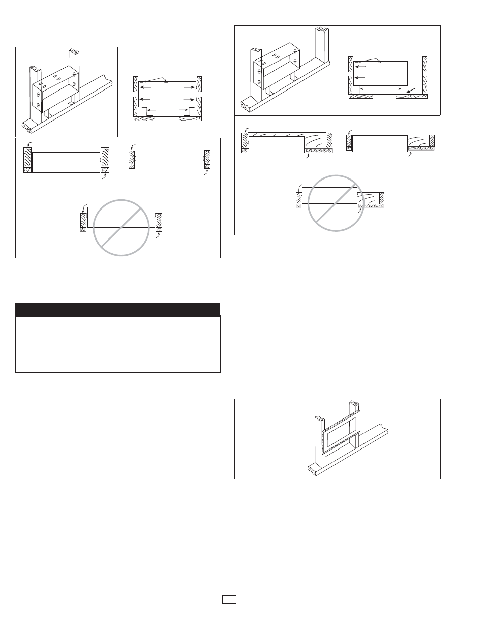
TO INSTALL BACK BOX (Model RBB)
IN NEW CONSTRUCTION - WALL STUDS 16” OC.
(REFER TO FIG. 1)
NOTE: Please review warning 12 on page 1.
1.
Locate back box (model RBB) and back box support brackets (2).
Back box must be installed with mounting rails to the top (see Fig.
1B).
2.
Install back box support brackets with foot tabs directed towards the
center of the back box as shown in Fig. 1A and 1B. It may be nec-
essary to bend up slightly the tab on the back box support bracket
to allow insertion under the mounting lances on the bottom of the
back box.
3.
Determine which knockout in back box will be used for field wiring
and remove (see back box drawing pg.1). Install strain relief (field
supplied). See warning No. 13.
4.
Fish field wiring through strain relief leaving 6” of wire inside box.
5.
Insert back box assembly into wall. The front of the back box should
be flush with the finished wall surface or it may protrude slightly. The
back box should never be recessed into the wall. (see Fig. 1C). The
back box support brackets should be resting on the sole plate of the
stud wall to insure proper spacing and leveling (see Fig. 1B).
6.
Using four (4) wood screws or drywall screws or four (4) nails (field
supplied), secure back box to studs (see Fig. 1B). Back box support
brackets can now be removed. If not removed, secure to sole plate.
TO INSTALL BACK BOX IN NEW CONSTRUCTION -
WALL STUDS SPACING GREATER THAN 16” OC.
(REFER TO FIG. 2)
NOTE: Please review warning 12 on page 1.
NOTE: Fig. 2 depicts the back box installed with the left side adjoining
stud. For a box with the right side adjoining a stud, reverse the directions
shown below.
1.
Locate back box and back box support brackets (2). Back box must
be installed with mounting rails to the top (see Fig. 2B)
2.
Determine which side of the back box will adjoin stud and insert back
box support bracket on that side with foot tab directed towards cen-
ter of back box. On the side of the back box that will not adjoin stud,
install back box support bracket on that side with foot tab directed
towards end of box and secure to box with 3/8” long sheet metal
screw (provided).
3.
Determine which knockout in back box will be used for field wiring
and remove (see back box drawing pg. 1). Install strain relief (field
supplied).
4.
Fish field wiring through strain relief leaving 6” of wire inside box.
5.
Insert back box assembly into wall. The front of the back box should
be flush with the finished wall surface or it may protrude slightly. The
back box should never be recessed into the wall. (see Fig. 2). The
back box support brackets should be resting on the sole plate of the
stud wall to insure proper spacing and leveling (see Fig. 2B).
6.
Use two (2) wood screws or drywall screws or two (2) nails (field
supplied) to secure the side of the back box that adjoins a stud. Use
one (1) wood screw or drywall screw or one (1) nail (field supplied)
to secure the foot tab of the back box support bracket (that is on the
end opposite the stud) to the sole plate (see Fig. 2B).
TO INSTALL BACK BOX IN
EXISTING CONSTRUCTION
NOTE: Please review warning 12 on page 1.
1.
Locate wall studs to be sure that entire cut-out can be made
between studs. At least one side of the cut-out must be flush with
side of the stud. Bottom of cut-out must be 4” above finished floor
minimum. Make a cut-out in wall 14-1/2” wide X 6-3/4” high (368mm
X 171mm) (see Fig. 3).
2.
Determine which knockout in back box will be used for field wiring
and remove (see back box drawing, pg.1). Install strain relief (field
supplied).
3.
Fish field wiring through strain relief leaving 6” of wire inside box.
4.
Insert back box into cut-out. The front of the back box should be
flush with the finished wall surface or it may protrude slightly. The
back box should never be recessed into the wall. (see Fig. 1C or
2C).
2
BACK BOX (FRONT VIEW)
NAIL OR SCREW
4 PLACES
BACK BOX
SUPPORT BKTS.
SOLE PLATE
STUD
STUD
MOUNTING RAILS
BACK BOX
TOP VIEW
INSERT FAN DECK
THIS SIDE
STUD
DRY WALL
BACK BOX
TOP VIEW
INSERT FAN DECK
THIS SIDE
STUD
DRY WALL
BACK BOX
TOP VIEW
INSERT FAN DECK
THIS SIDE
STUD
DRY WALL
BACK BOX
TOP VIEW
INSERT FAN DECK
THIS SIDE
STUD
DRY WALL
INSERT FAN DECK
THIS SIDE
STUD
DRY WALL
BACK BOX
TOP VIEW
INSERT FAN DECK
THIS SIDE
STUD
DRY WALL
BACK BOX
TOP VIEW
Figure 1A
Figure 1B
Figure 1C
BACK BOX (FRONT VIEW)
NAIL OR SCREW
BACK BOX
SUPPORT BKTS.
SOLE PLATE
NAIL OR SCREW
STUD
STUD
MOUNTING RAILS
Figure 2A
Figure 2B
Figure 3
CORRECT
CORRECT
INCORRECT
Figure 2C
CORRECT
CORRECT
INCORRECT
The “IF” models do not include a backbox. The Backbox is
ordered separately. In the parts bag for “IF” models, there is a
white label that indicates multiple wattage and must be place
in the backbox on the bottom right-hand side. When making
wattage changes, the installer must circle the wattage on the
white label before installing the heat deck.
NOTE TO INSTALLER