Qmark FRP/FRS - 2 & 3 Element Infrared Heaters User Manual
Page 2
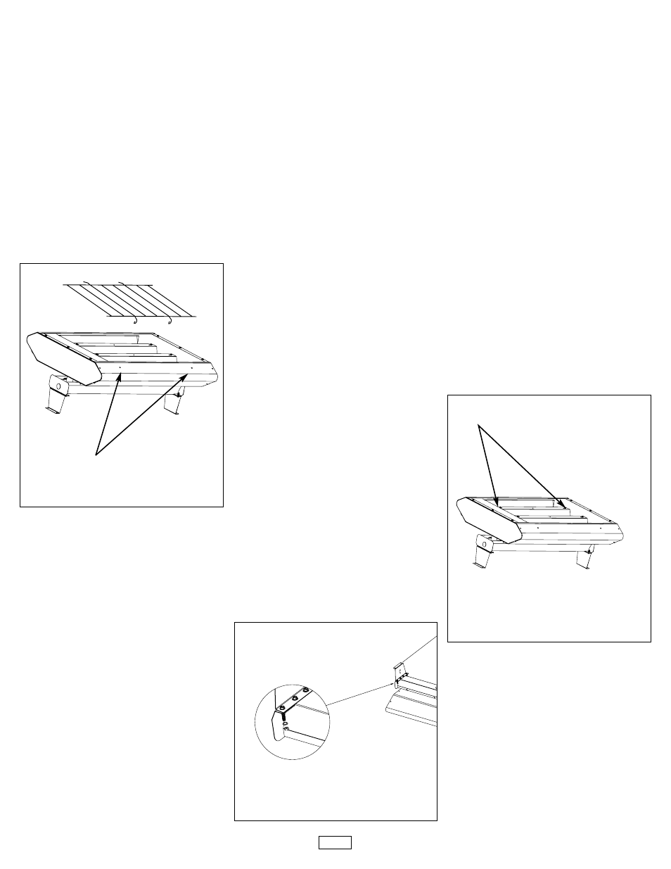
WIRE GUARD
Reference Figure 1.
1. Drill
5
/
32
”
diameter holes at the
dimple locations shown.
2. Install heating elements in
accordance with the instruc-
tions provided with the ele-
ments.
3. Position wire guard onto heater
as shown and attach to heater
(into the
5
/
32
” holes drilled in
step 1) using the #10 scews
provided.
4. Secure wire guard to heater
using #10 screws provided.
RED VYCOR SLEEVE
Note: To be used on Quartz
Lamp elements only.
Do NOT handle Quartz lamp
elements with bare hands, as
salt in perspiration may deterio-
rate the quartz and result in a
premature failure.
1. Attach one end of quartz lamp
element as indicated by instruc-
tions supplied with elements.
2. Carefully slide Red Vycor
Sleeve over element.
3. Position element in reflector
and continue with element
installation, as indicated by
instructions supplied with ele-
ments.
ADJUSTABLE TILT
MOUNTING BRACKET
Adjustable Tilt Mounting
Brackets replace the mounting
brackets supplied with the
heater enclosure.
Reference Figure 2.
1. Determine mounting location
as indicated by instructions
supplied with heater enclosure.
2. Do NOT attach originally sup-
plied mounting brackets.
3. On a workbench or other flat
surface, attach Adjustable Tilt
Mounting Brackets to ends of
wireway cover using bolts, star
washers and nuts supplied with
heater enclosure.
4. Remove wireway cover/mount-
ing brackets from wireway
base, as indicated by instruc-
tions supplied with heater
enclosure.
5. Mount wireway cover/mounting
brackets to ceiling and secure
using fasteners sized to suffi-
ciently support heater and any
optional accessories used.
6. Proceed with heater installation
as indicated by instructions
supplied with heater enclosure.
GOLD ANODIZED
REFLECTORS
Reference Figure 3.
1. Place the heater enclosure on
a workbench or other flat sur-
face.
2. If elements are installed,
remove them at this point.
Reflector can not be replaced
with elements installed.
3. Remove the reflector attach-
ment screws and keep for
reuse.
4. Applying light pressure, push
down on the bottom of one side
reflector until reflector end is
free from enclosure.
5. Rotate reflector away from
enclosure.
6. Install replacement reflector in
opposite sequence.
2
Drill Dimple Location
Typical
Reflector Attachment Screw
Typical
(2 on 2 element heaters)
(4 on 3 element heaters)
Figure 1
Figure 3
(Typical 4 Locations)
Figure 4A
Figure 2