Qmark Open Coil Electric Duct Heaters User Manual
Page 3
8. Fasten the heater to the duct with sheet metal screws. (For
heavy heaters, use nuts and bolts and additional hangers to
support the heater).
9. Seal openings with a suitable sealing compound.
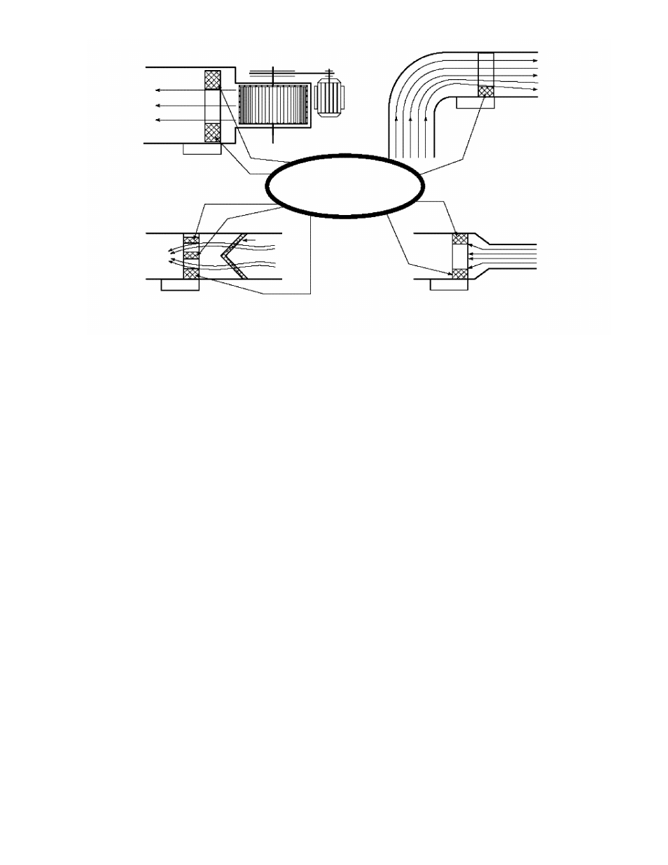
10. Spacing Requirements to obtain Optimal Operating Conditions
(Please see drawings page 4).
• 24 inches between the heater and filter frames.
** inches between the heater and elbows in the duct.
** inches between the heater and branches in the duct.
** inches between the heater and sharp transitions of
the
duct.
** = minimum distance = the largest of two dimensions
(W or H) up to 48”.
Examples: heater of 12” x 12”
minimum
distance
12”.
heater of 30” x 12”
minimum
distance
30”.
Heater of 60” x 30”
minimum distance 48”.
• 48 inches between the heater and a double outlet fan,
(except with split duct design)
• 24 inches between the heater and access doors or
diffusers, (except if a metal screen is supplied with the
heater.
• 1 inch between the duct at the outlet side and combustible
materials for a length of 72 inches, (for vertical ducts only).
• For the flanged type, 24 inches between the control box
cover and obstructions to allow space for installation and
service.
• For the slip-in type, width of the duct (dimension W) + depth
of the control box + ten (10) inches between the control box
cover and obstructions to allow slipping the heater out the
duct and to allow safe servicing.
Electrical Installation of Heaters
1. Disconnect all power sources before opening the control box
and working within.
2. Read the nameplate carefully and consult wiring diagram
included with the unit before starting to wire.
3. Use only wires suitable for 75°C. Wires shall be sized accord-
ing to the National Electrical Code requirements. All wires must
be brought in through knock-outs.
4. Install a disconnect switch close to the heater according to the
code unless a disconnect switch is already built into the heater.
5. Use class 2 wiring for control circuit connections to the duct
heater.
6. If magnetic contactors are mounted outside of the duct heater,
use only contactors approved for the following:
• 250,000 operations when controlled by auto-reset thermal
cut-out (A) and by other switching devices in series with this
cut-out (thermostat, step controller, air flow switch, etc.).
• 100,000 operations when controlled by auto-reset thermal
cut-out (A) alone.
• 100,000 operations when controlled by auto-reset thermal
cut-out (A) plus manual reset cut-out in series.(A&M).
• 6,000 operations when controlled by manual reset cut-out
(M) alone.
7. Rating of external control devices shall be suitable for handling
the VA ratings as marked on the nameplate, otherwise, a
back-up relay must be used.
8. Heaters are generally supplied with one extra terminal marked
(I) for fan interlock or air sensing device connection. Remove
jumper between terminals I and C before connecting the fan
interlock, Select a suitable air flow sensing device of the
differential pressure sensing type, with snap acting contacts. A
slow make, slow brake device may cause undue cycling and in
some instances chattering of the contactors. When fresh air
dampers are used, make sure the heater is properly
interlocked to prevent it from being energized before the
damper is fully open.
3
Avoid
these overheating
conditlions
Heater too close to a fan
Heater too close to an elbow
Heater too close to a filter
Figure 5: Overheating Conditions -
Heater shouldn't be installed closer than 4' downstream or 2' upstream from a fan outlet or any obstruction in the duct work.
Heater too close to a trasition