Wa ll floor – Qmark DBA - Architectural Sill-Height Convection Heaters User Manual
Page 4
pedestal mounted, consult pedestal kit installation instruc-
tions.
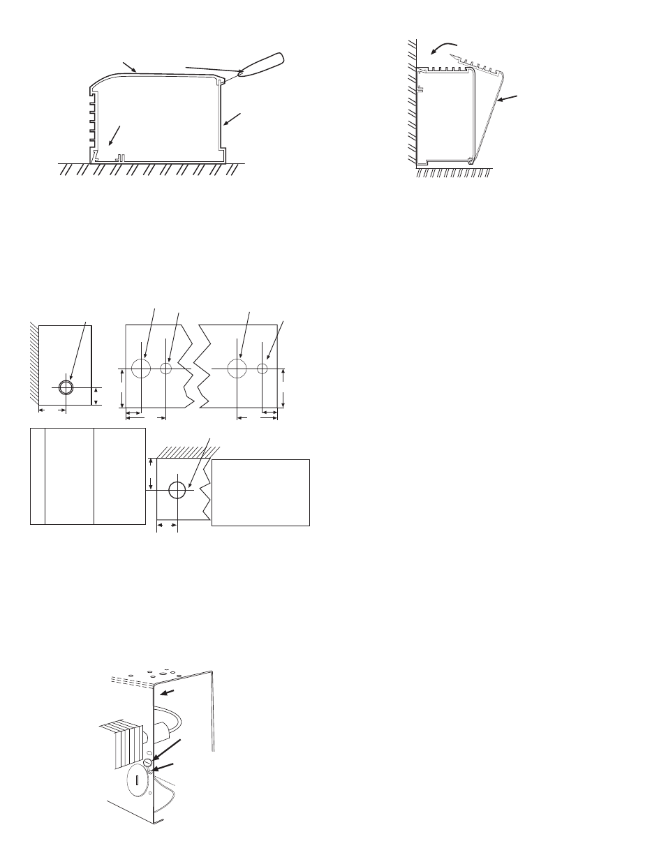
4. Drill the required size mounting holes in the heater housing
(See Fig. 1 for recommended mounting hole location.)
5. Hold heater housing against the wall to check for evenness
of wall. Do not draw heater against an uneven wall surface. If
an uneven wall is encountered, use shims to keep the heater
housing straight.
6. Run proper size branch circuit to the junction box through the
selected knockout.
7. Mount the heater on the wall using screws, bolts or anchors
(by installer) to suit the wall construction.
8. Tighten mounting screw and back off 1/2 turn to allow for
expansion and contraction of the heater.
9. Following the wiring diagram secured to the heater, make
electrical connections. Ground the heater using the ground
screw provided. See Fig. 3.
10.Replace front cover by latching the bottom front edge of the
front cover over the bottom front edge of the back and push-
ing the cover straight back to latch the top rear edge of the
back with the top rear edge of the front cover. See Fig. 4.
Installation of Multiple Wall to Wall Units
NOTE: For ease of installation, it is important that the sequence
of operations indicated below be followed in order.
1. Repeat Steps 1 & 2 from Single Unit Installation.
2. Refer to wiring diagram for power supply entry and remove
appropriate electrical knockout (Fig. 2) from the heater in
which power supply connections are to be made. The power
supply may be brought into the end of one heater and the
remaining heaters may be connected in parallel using the
wireway. Use Table B to size the field installed wiring in the
wireway or use Table C to determine the maximum length or
heater run possible using the factory installed wire in the
heater wireway. If units are to be pedestal mounted, consult
pedestal kit installation instructions.
3. If filler sections, inside corners, outside corners, splice kits or
end caps are to be used, consult accessory installation
instructions.
NOTE: If a heater has a disconnect switch and/or thermostat
and is to have a filler section at the left end, the filler must not
cover the access to those controls.
4. If the run of the heaters includes an inside corner or an out-
side corner, mount corner to wall (see accessory installation
instructions packed with corners), then mount heater.
5. Drill the required size mounting holes in all the heater hous-
ings. (See Fig. 1 for recommended mounting hole location.)
6. Hold heater housings against wall to check for evenness of
the wall. Do not draw the heaters against an uneven wall
surface. If an uneven wall is encountered, use shims to keep
the heater housing straight.
7. Run proper size branch circuit to the junction box through the
selected knockout.
8. Mount the heaters on the wall using screws, bolts or anchors
(by installer) which suit the wall construction. Alignment tabs
can be inserted in adjoining back housings to assure even
alignment. See Fig. 5 for details.
9. Following the wiring diagram secured to the heater, make the
electrical connections. Refer to Fig. 7 to connect the other
heaters in parallel. Grounding of the other heaters is accom-
plished by connecting a jumper wire (not supplied) between
the two adjacent heaters.
10.Replace front covers following Step 10, Single Unit
Installation (See Fig. 4.)
4
W
a
ll
Floor
Junction
Box
Ground
Screw
Run ground
wire thru top
or bottom hole.
Wrap around
ground screw
and tighten
screw.
Fig. 3
W
a
ll
Floor
Junction
Box
Ground
Screw
Run ground
wire thru top
or bottom hole.
Wrap around
ground screw
and tighten
screw.
Fig. 4
Cabinet front
cover
Putty knife or
other wide blade
tool
}
Cabinet
Back
Housing
Recommended
mounting holes
drill area
Fig. 1
Y
X
E
D
C
E
H
W
B
A
7/8” (22mm) and
1-1/8” (29mm)
concentric KO’s
1-3/8”
(35mm)
KO
7/8”
(22mm)
KO
7/8”
(22mm)
KO
1-3/8”
(35mm)
KO
1-23/32”
(44mm)
KO
Fig. 2
2” (51)
2-1/4”(28)
7/8” (22)
2-1/4”(28)
3-3/8”(86)
1-11/32”(34)
1-7/8”(48)
1-3/16”(81)
2-9/16”(28)
2-25/32” (71)
2-1/4”(28)
7/8” (22)
2-1/4”(28)
3-3/8”(86)
2” (51)
2-3/8”(60)
1-3/16”(81)
2-9/16”(28)
in. (mm)
DBA SHA
Pedestal placement and
KOs shown are for standard
units. Custom enclosures
and/or heat decks will have
pedestal placement and
KOs in various locations.
Consult factory.
A
B
C
D
E
H
W
X
Y