Table a - slqdb, Clearance chart, Technical data) – Qmark SLQDB - Draft Barrier Heaters User Manual
Page 2: Table b. sizing field installed wiring, Fig. 1: clearance for drapery example 1 example 2
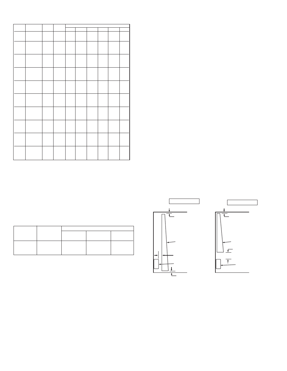
Clearance Chart:
For safe and efficient operation, maintain at least the following
minimum clearances at all times(see Fig. 1):
Bottom of Heater to Finished Floor:
• For models 188 watts per foot or more, bottom of units must
be mounted at least 2” off floor.
• Bottom Inlet Models:
- 100-188 watts per foot – 2 inch (51 mm)
Top of Heater to Ceiling (all models):
- Minimum 36 inches (914 mm)
Top of Heater to Bottom of Drapes (See Example 2):
- Minimum 6 inches (152 mm)
IMPORTANT NOTE: Certain fabrics and vinyl materials (such
as vinyl blinds) may become damaged by the heated air from
the heater and should not be installed above the heater.
Front of Heater to Full Length Drapes (See Example 1):
- Minimum between bottom of drapes and floor – 2-1/2 inches
(64 mm)
- Minimum between top of drapes and ceiling – 1/2 inch (13
mm)
- Minimum between front of heater and nearest fold of drape –
2 inches (51 mm)
Top of Heater to Bottom of Window Sill:
- Minimum 12 inches (305 mm)
2
No. 12 AWG
No. 10 AWG
No. 8 AWG
5
4
2
7 Amps
9 Amps
12.0 Amps
5 Amps
7 Amps
10 Amps
4.5 Amps
6 Amps
-
Copper wire
size 90º C
Max. No.
wire installed
in wireway
Up to 2
conductors
3 to 4
conductors
4 to 5
conductors
Maximum Allowable Current
Table B. Sizing Field Installed Wiring
Catalog
Length
Watts
Total
Amperage
Number
"L"
per ft.
Watts
120V
208V
240V
277V
347V
600V
22100
100
200
--
1.0
--
--
--
--
22150
24”
150
300
2.5
1.4
1.3
--
--
--
22188
(610mm)
188
376
3.1
1.8
1.6
1.4
--
--
02100
100
200
1.7
1.0
0.8
--
--
--
02125
28"
125
250
2.1
1.2
1.0
0.9
--
--
02150
(711mm)
150
300
2.5
1.4
1.3
1.1
--
--
02188
188
376
3.1
1.8
1.6
1.4
--
--
03100
100
300
2.5
1.4
1.3
1.1
--
--
03125
3'
125
375
3.1
1.8
1.6
1.4
1.1
--
03150
(914mm)
150
450
3.8
2.2
1.9
1.6
1.3
--
03188
188
564
4.7
2.7
2.4
2.0
1.6
--
04100
100
400
3.3
1.9
1.7
1.4
1.2
--
04125
4'
125
500
4.2
2.4
2.1
1.8
1.4
--
04150
(1219mm)
150
600
5.0
2.9
2.5
2.2
1.7
--
04188
188
752
6.3
3.6
3.1
2.7
2.2
1.3
05100
100
500
4.2
2.4
2.1
1.8
1.4
0.8
05125
5'
125
625
5.2
3.0
2.6
2.3
1.8
1.0
05150
(1524mm)
150
750
6.3
3.6
3.1
2.7
2.2
1.3
05188
188
940
7.8
4.5
3.9
3.4
2.7
1.6
06100
100
600
5.0
2.9
2.5
2.2
1.7
1.0
06125
6'
125
750
6.3
3.6
3.1
2.7
2.2
1.3
06150
(1829mm)
150
900
7.5
4.3
3.8
3.2
2.6
1.5
06188
188
1128
9.4
5.4
4.7
4.1
3.3
1.9
07100
100
700
--
3.4
2.9
2.5
2.0
1.2
07125
7'
125
875
--
4.2
3.6
3.2
2.5
1.5
07150
(2134mm)
150
1050
--
5.0
4.4
3.8
3.0
1.8
07188
188
1316
--
6.3
5.5
4.8
3.8
2.2
08100
100
800
--
3.8
3.3
2.9
2.3
1.3
08125
8'
125
1000
--
4.8
4.2
3.6
2.9
1.7
08150
(2438mm)
150
1200
--
5.8
5.0
4.3
3.5
2.0
08188
188
1504
--
7.2
6.3
5.4
4.3
2.5
09100
100
900
--
4.3
3.8
3.2
2.6
1.5
09125
9'
125
1125
--
5.4
4.7
4.1
3.2
1.9
09150
(2743mm)
150
1350
--
6.5
5.6
4.9
3.9
2.3
09188
188
1692
--
8.1
7.1
6.1
4.9
2.8
10100
100
1000
--
4.8
4.2
3.6
2.9
1.7
10125
10'
125
1250
--
6.0
5.2
4.5
3.6
2.1
10150
(3048mm)
150
1500
--
7.2
6.3
5.4
4.3
2.5
10188
188
1880
--
9.0
7.8
6.8
5.4
3.1
Table A - SLQDB
(Technical Data)
CEILING
FLOOR
FLOOR
DRAPES
HEATER
W
A
L
L
W
A
L
L
CEILING
MIN. 1/2”
(13 mm)
MIN. 2”
(51 mm)
MIN. 2-1/2”
(64 mm)
MIN. 1/2”
(13 mm)
MIN. 6”
(152 mm)
HEATER
DRAPES
Fig. 1: Clearance for Drapery
Example 1
Example 2