Operation instructions – Qmark SSHO Smart Series - High Out-Put Digital Wall Heater User Manual
Page 4
Wiring of Heater
Refer to Wiring Diagram, Figure 4
1. Connect the black (L1) heater pigtail from ON/OFF switch to
the black power lead on the heater assembly.
2. Connect the red (L2) heater pigtail to the other black power
lead.
NOTE: L2/N heater pigtail is white for 277 volt model and must
be connected (through ON/OFF Switch) to a white Neutral
supply lead.
3. If not already done, connect building ground conductor to
green ground screw in heater back box.
Building Management Systems (BMS)
To utilize the BMS capabilities of this unit, remove the red
jumper wire between terminals A and B on the control terminal
board ( see figure 3, wiring diagram). Connect two wires from a
dry contact (no voltage) in the BMS system to terminals A and B.
NOTE: DO NOT REMOVE THE RED JUMPER UNLESS
CONTROL BY A BUILDING MANAGEMENT SYSTEM IS BEING
USED.
When BMS takes control, heater functions will not work, the
touch screen is locked, BMS light on the heater touchscreen
blinks.
When BMS releases control, heater functions are available,
heater resumes operating at previously programmed settings.
Refer to Operations Manual for programming options and details.
Installation of Grille and Control Wire Connector
1. Push ON/OFF switch into ON position.
2. Install (2) plastic covers on back box as follows:
(See Figure 5)
NOTE: Both top and bottom plastic covers are identical.
• TOP - Align the screw bosses on the back of the plastic
cover with the second hole down from the top of the back
box and attach it with the two screws provided.
• BOTTOM - Align the screw bosses on the back of the
second plastic cover with holes at the bottom of the back
box that are just above the fan deck mounting screws and
attach it with two screws provided.
3. Position the grille in front of the heater assembly, extend the
control wire connector from the heater assembly to the
matching connector from the back of the electronic control,
behind the grille. The connector is keyed so it will fit only one
way.
NOTE: Press the connector gently and firmly, but do not force,
making sure the clip on the connector engages.
4. Install the front cover by hooking the (2) tabs on top and
bottom plastic covers on one side then rotating the front
cover into place making sure that all four tabs are snapped
into the grille.
NOTE: Use caution when installing the grille to avoid trapping
the control wire in between the grille and heater assembly.
OPERATION
INSTRUCTIONS
Initial Setup Instructions (Performed by Installer)
NOTE: After installation, the installer should perform the follow-
ing procedures to ensure proper operation of the heater. See
“Customizing Heater Settings” for details on programming other
functions of the heater.
1. Switch the power on at the main circuit panel. When the
heater is first powered up the buzzer beeps for one second
and displays all indicators in high luminance and the POWER
button in half blue luminance for 3 seconds, then the unit will
turn OFF. When OFF, only the POWER button illuminates in
orange color in half luminance and all other buttons and
icons will be OFF. When OFF, if the POWER button is
touched, all 4 buttons will illuminate indicating the heater is
ON and the control panel is powered up. See Figure 6 for
Control Panel layout details.
POWER SUPPLY VOLTAGE MUST BE THE SAME AS
HEATER VOLTAGE RATING SHOWN ON HEATER NAME-
PLATE. CONNECTING TO A VOLTAGE IN EXCESS OF
NAMEPLATE RATING WILL DAMAGE HEATER AND VOID
WARRANTY. ALL CONNECTIONS MUST BE MADE WITH
APPROPRIATELY SIZED LISTED WIRE CONNECTORS.
4
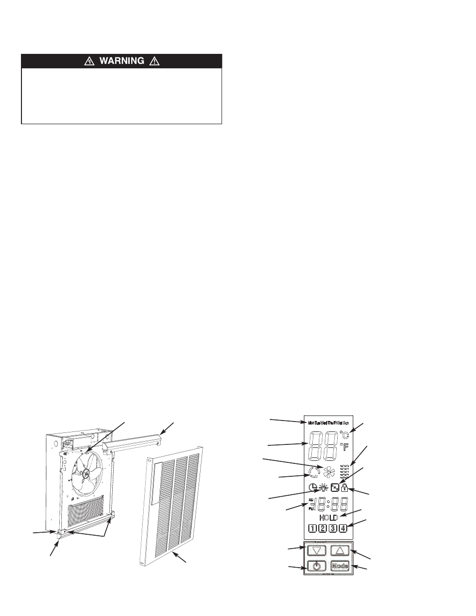
Figure 6 - Control Panel
Temperature
Down Button
Automatic mode
indicator
Nightlight
indicator
Time
Day indicator
(also used when program-
ming custom periods)
Heat control
indicator
Fan Speed
indicator
Building Management
System indicator
Hold indicator
Lock Out indicator
Time periods:
1- Wake up
2- Daytime
3- Evening
4- Sleep
Centigrade /
Fahrenheit indicator
Power Button
Mode Button
Up Button
Figure 5 - Installation of Grille Assembly
Plastic Cover
Wire Connector
Grille
Plastic Cover
Tab
Screws