Qmark Mechanical Artisan - Heavy-Duty Architectural Wall Heater User Manual
Page 4
Building Management Systems (BMS)
To utilize BMS capabilities of this unit, there are two (optional)
accessories available. Model WHR2A which has a 24 volt hold-
ing coil can switch the heaters ON/OFF from remote source.
Model WHR12A which has a 120 volt holing coil can switch the
heaters ON/OFF from remote source.
Refer to the control installation manual when installing.
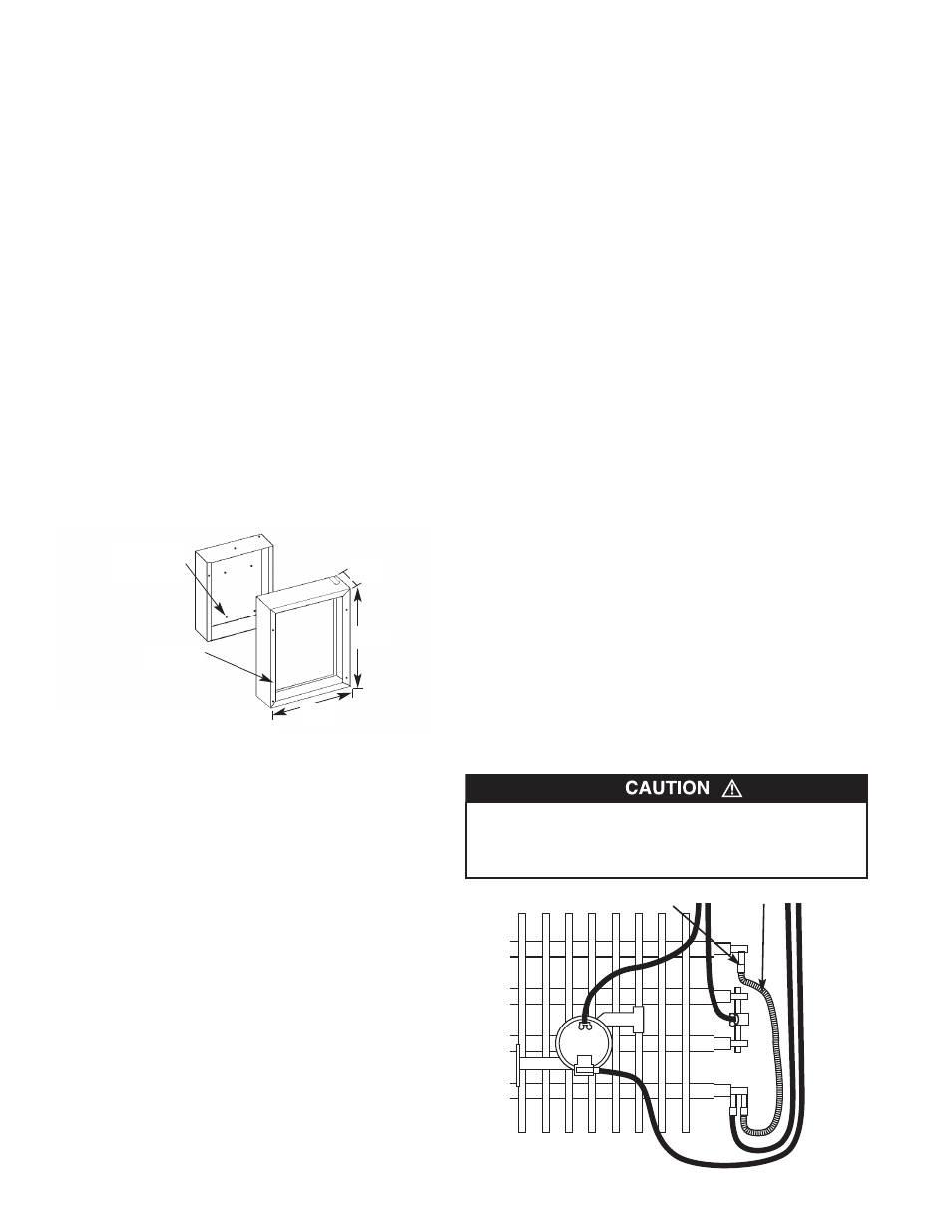
Installation of Back Box with Optional
Surface-Mounting Frame HTWHSM (See Figure 4)
1. Secure back box to wall with knockouts in upper right hand
corner using screws and anchors.
2. Hang the surface-mounting frame on the back box. Ensure
that the back edge of the surface-mounting frame is flush
against the wall.
NOTE: If heater is located in a high traffic area, where it may be
subjected to vandalism or abuse, take extreme care to see that
the back box is firmly attached to the wall.
3. Power Supply Wiring
NOTE: Wiring Compartment Volume - 119in3 (1950cm3).
a. Run a power supply cable into the area to the right of the
mounting frame. Arrangement of wiring to this point must
be in accordance with National and Local codes. Refer to
Table 1 on page 1 for proper wire size.
NOTE: If the wiring is to run through the wall, cut a hole I in the
area of the top right corner of the back box. Run the supply wire
through this hole. Then remove the “knockout” from the top of the
box and proceed to step C.
c. Remove disconnect switch bracket by loosening the two
screws on the right side.
d. Feed the power supply cable through the frame allowing
6in (152mm) of lead to remain inside the back box (using a
cable clamp, connector, or other suitable strain relief)
e. Secure the power supply cable to the back box (using
cable clamp, connector, or other suitable strain relief)
allowing 6in (152mm) of lead to remain inside the back
box.
f. Connect supply wires to blue wires of disconnect switch
using wiring connectors (see wiring diagram 3, Page 3).
g. Ground the back box by connecting the supply ground
lead wire to the green ground screw located in the inside
top of the back box.
h. Feed remaining 2 wires from disconnect switch through
hole in the switch bracket and secure disconnect switch
bracket in place.
Installation of Heater / Grille into Back Box
Note to Installer: Converting heater to half wattage
(Not applicable to MCARWH1802 120 Volt Models)
The MCARWH Series wall heaters are manufactured and
shipped at the higher rated wattage. Full wattage heaters can be
converted to half wattage by doing the following steps.
1. Remove the red jumper wire as shown in Figure 5 and dis-
card.
2. To permanently make the heater half wattage, cut the male
terminal spade, carefully not to damage the cold pin and dis-
card.
3. Mark the wattage of the heater on the white label inside the
back box.
After back box is completely installed and no further construction
dirt is expected, clean debris from back box and remove heater
assembly from its carton.
1. Lift and rotate the grille assembly into the back box carefully
to ensure the wiring is not trapped between the grille assem-
bly and back box. Position the grille assembly in front of the
back box and insert Control Shelf into the notches on either
side of the back box. At the same time hooking the tabs on
the bottom corners of the grille assembly over the bottom
flange of the back box. Refer to figures 6 and 7..
2. With the top of the grille assembly leaning forward, supported
by the first notch in control shelf, extend the lead wires from
the back of the top of the heater grille assembly to the (2)
power wires of the disconnect switch assembly and connect
according to Wiring Diagram shown in Figure 3 (page 3)
3. If a surface mounting frame is used, ensure that the frame is
even with all four sides of the heater.
4. Connect the two disconnected switch wires to the heater
wires using wire nuts (provided). After the connection, care-
fully push wires back into the opening.
5. Turn thermostat to the extreme counterclockwise position in
OFF position.
6. Push disconnect switch to ON position.
7. Tighten top cover screws down to hold grille in place.
See Figure 8.
4
Male terminal spade
Red jumper wire
Figure 5- Jumper Wire Location
Figure 4 - Surface Mounting Installation
MOUNT BACK BOX
TO WALL USING
REAR MOUNTING
HOLES.
HANG FRAME
ON BACK BOX.
15-5/32 "
(385mm)
19"
(482mm)
3-13/16"
(97mm)
THE HEATER ASSEMBLY MUST BE CAREFULLY POSI-
TIONED TO ENSURE THE CONTROL WIRES ARE NOT
TRAPPED BETWEEN THE HEATER ASSEMBLY AND THE
BACK BOX.