Pin definitions – Cypress CY7C1165V18 User Manual
Page 7
CY7C1161V18, CY7C1176V18
CY7C1163V18, CY7C1165V18
Document Number: 001-06582 Rev. *D
Page 7 of 29
CQ
Echo Clock
Synchronous Echo Clock Outputs. This is a free running clock and is synchronized to the input
clock (K) of the QDR-II+. The timings for the echo clocks are shown in
ZQ
Input
Output Impedance Matching Input. Used to tune the device outputs to the system data bus
impedance. CQ, CQ and Q
[x:0]
output impedance are set to 0.2 x RQ, where RQ is a resistor
connected between ZQ and ground. Alternatively, this pin is connected directly to V
DDQ
, which
enables the minimum impedance mode. This pin cannot be connected directly to GND or left uncon-
nected.
DOFF
Input
DLL Turn Off
− Active LOW. Connecting this pin to ground turns off the DLL inside the device. The
timings in the DLL turned-off operation are different from those listed in this data sheet. For normal
operation, this pin is connected to a pull up through a 10 K
Ω or less pull up resistor. The device
behaves in QDR-I mode when the DLL is turned off. In this mode, the device operates at a frequency
of up to 167 MHz with QDR-I timing.
TDO
Output
TDO for JTAG.
TCK
Input
TCK Pin for JTAG.
TDI
Input
TDI Pin for JTAG.
TMS
Input
TMS Pin for JTAG.
NC
N/A
Not Connected to the Die. Can be tied to any voltage level.
NC/36M
N/A
Not Connected to the Die. Can be tied to any voltage level.
NC/72M
N/A
Not Connected to the Die. Can be tied to any voltage level.
NC/144M
N/A
Not Connected to the Die. Can be tied to any voltage level.
NC/288M
N/A
Not Connected to the Die. Can be tied to any voltage level.
V
REF
Input-
Reference
Reference Voltage Input. Static input used to set the reference level for HSTL inputs, outputs, and
AC measurement points.
V
DD
Power Supply Power Supply Inputs to the Core of the Device.
V
SS
Ground
Ground for the Device.
V
DDQ
Power Supply Power Supply Inputs for the Outputs of the Device.
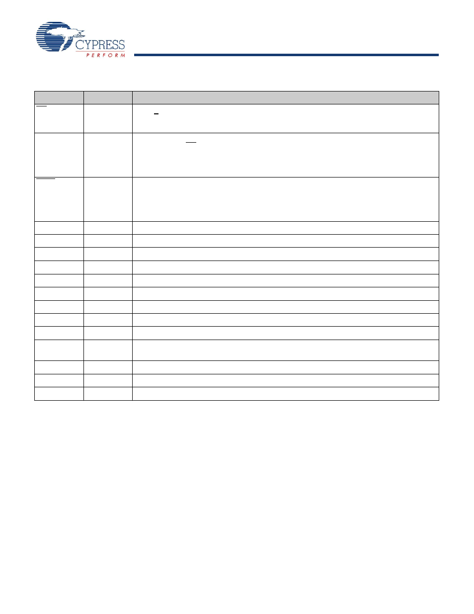
Pin Definitions
(continued)
Pin Name
IO
Pin Description