Server module messages, Table 2 – Dell POWEREDGE 1855 User Manual
Page 25
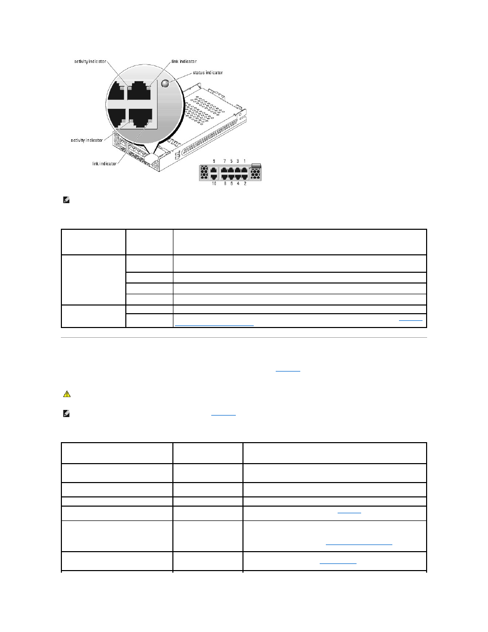
Table 2-13. Gb Pass-through Module Indicators
Server Module Messages
System messages appear on the screen to notify you of a possible problem with the system.
lists the system messages that can occur and the
probable cause and corrective action for each message.
Table 2-14. Server Module Messages
NOTE:
Connectors on the Gb pass-through module correspond directly to the server module number. For example, server module 5 is connected to port
5 on the Gb pass-through module.
Indicator Type
Activity
Indicator
Indicator Code
Link indicator/activity
indicator
Green/amber
blinking
The Gb Ethernet connector is linked to the server module and there is network activity
Green/off
The Gb Ethernet connector is linked to the server module and there is no network activity.
Off/amber blinking The Gb Ethernet connector is not linked to the server module and there is network activity.
Off/off
The Gb Ethernet connector is not linked to the server module and there is no network activity.
Status indicator
Green
Module is operating correctly.
Green blinking
Module is being powered down by the DRAC/MC controller due to an I/O module mismatch. See "
for Installing Connectivity Modules
CAUTION:
Many repairs may only be done by a certified service technician. You should only perform troubleshooting and simple repairs as
authorized in your product documentation, or as directed by the online or telephone service and support team. Damage due to servicing that is not
authorized by Dell is not covered by your warranty. Read and follow the safety instructions that came with the product.
NOTE:
If you receive a system message that is not listed in
, check the documentation for the application that is running when the message
appears or the operating system's documentation for an explanation of the message and recommended action.
Message
Causes
Corrective Actions
Amount of available memory limited to
256MB!
OS Install Mode is enabled
in the System Setup
program.
Disable OS Install Mode in the System Setup program. See "Using the
System Setup Program" in your User's Guide.
Attempting to update Remote Configuration.
Please wait....
Remote Configuration is in
progress.
Wait until the process is complete.
BIOS Update Attempt Failed
BIOS remote update failed.
Retry update.
Caution! NVRAM_CLR jumper is installed on
system board.
NVRAM_CLR switch is set to
"on."
Set the NVRAM_CLR switch to "off." See
Figure A
-2
for the jumper location.
CD-ROM drive not found
Improperly connected or
missing CD drive.
If no custom cable is installed, disable the IDE controller. See "Using the
System Setup Program" in the User's Guide.
If an optical drive is installed, see "
Troubleshooting USB Devices
" in
"Troubleshooting Your System."
CPUs with different cache sizes detected.
Mismatched processors are
installed.
Install a correct version of the microprocessor so that both microprocessors
have the same cache size. See "
Microprocessors
" in "Installing System
Options."