Powerconnect 5316m ethernet, Switch module, Fibre channel pass-through module – Dell POWEREDGE 1855 User Manual
Page 23: Powerconnect 5316m ethernet switch module
PowerConnect 5316M Ethernet Switch Module
The PowerConnect 5316M Ethernet switch module is a 16-port switch with 6 uplinks and 10 downlinks (see
). The uplinks connect to the external
Ethernet network and operate at 10/100/1000 Mb. The downlinks connect to the embedded Ethernet controller on the server module and operate at 1000 Mb
only.
The PowerConnect 5316M Ethernet switch module is hot-pluggable. To provide connectivity into separate Ethernet networks, two switch modules can be
installed in bays I/O 1 and I/O 2 (see
not required, the switch module must be installed in I/O 1 bay. The switch module has an internal serial port that communicates with the DRAC/MC module.
lists the indicators on each switch module. For additional information about the PowerConnect 5316M Ethernet switch module, see the
documentation that shipped with the module.
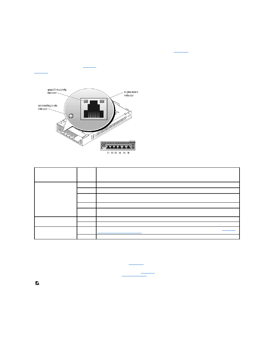
Figure 2-12. PowerConnect 5316M Ethernet Switch Module Indicators and Features
Table 2-11. PowerConnect 5316M Ethernet Switch Module Indicators
Fibre Channel Pass-Through Module
The Fibre Channel pass-through module provides a bypass connection between the Fibre Channel daughter card in the server module and optical transceivers
for direct connection into a Fibre Channel switch or a storage array. (see
). The Fibre Channel pass-through modules are hot-pluggable. The Fibre
Channel pass-through module in I/O bay 3 connects to port 1 on the optional Fibre Channel daughter card installed in a server module. The Fibre Channel
pass-through module in I/O bay 4 connects to port 2 on the optional Fibre Channel daughter card installed in a server module. To provide redundancy, both
I/O bay 3 and I/O bay 4 must have Fibre Channel pass-through modules installed.
lists the functionality of the Fibre Channel pass-through module
indicators. For additional information on installing this module, see "
Chassis I/O Module
" in "Installing System Options."
Figure 2-13. Fibre Channel Pass-through Module Indicators and Features
Indicator Type
Activity
Indicator
Indicator Code
Speed/link activity indicator
(bicolor)
Off
Not connected.
Green
The port is connected to a valid link partner on the network.
Green
blinking
Network data is being sent or received at 1 Gb.
Amber
The port is connected to a valid link partner on the network.
Amber
blinking
Network data is being sent or received at 10 Mb or 100 Mb.
Duplex mode indicator
Green
The port is operating at full duplex mode.
Off
The port is operating at half duplex mode.
System/diagnostic indicator
Green
blinking
Module is being powered down by the DRAC/MC controller due to an I/O module mismatch. See "
for Installing Connectivity Modules
Off
Module is operating normally.
NOTE:
The Fibre Channel pass-through module includes Short Wave Small Form Factor Pluggable (SFP) optical transceivers. To ensure proper
functionality, use only the SFPs provided with this module.