Processor module, Removing the processor module – Dell Alienware M18x (Early 2011) User Manual
Page 14
Back to Contents Page
Processor Module
Alienware M18x Service Manual
Replacing the Processor Module
Removing the Processor Module
1.
Follow the instructions in
Before You Begin
.
2.
Remove the battery pack (see
Removing the Battery Pack
).
3.
Remove the base cover (see
Removing the Base Cover
).
4.
Remove the center control cover (see
Removing the Center Control Cover
).
5.
Remove the keyboard (see
Removing the Keyboard
).
6.
Remove the macro keyboard (see
Removing the Macro Keyboard
).
7.
Remove the display assembly (see
Removing the Display Assembly
).
8.
Follow the instructions from
step 10
to
step 16
in
Removing the Palm Rest
.
9.
Remove the processor heat-sink (see
Removing the Processor Heat-Sink
).
10.
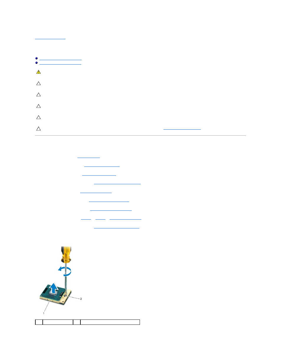
To loosen the ZIF socket, use a small, flat-blade screwdriver to rotate the ZIF-socket cam screw counterclockwise until it comes to the cam stop.
WARNING:
Before working inside your computer, read the safety information that shipped with your computer. For additional safety best
practices information, see the Regulatory Compliance Homepage at www.dell.com/regulatory_compliance.
CAUTION:
Only a certified service technician should perform repairs on your computer. Damage due to servicing that is not authorized by Dell is
not covered by your warranty.
CAUTION:
To avoid electrostatic discharge, ground yourself by using a wrist grounding strap or by periodically touching an unpainted metal
surface (such as a connector on your computer).
CAUTION:
To prevent intermittent contact between the ZIF-socket cam screw and the processor module when removing or replacing the
processor, press to apply slight pressure to the center of the processor module while turning the cam screw.
CAUTION:
To avoid damage to the processor module, hold the screwdriver so that it is perpendicular to the processor module when turning the
cam screw.
CAUTION:
To help prevent damage to the system board, remove the main battery (see
Removing the Battery Pack
) before working inside the
computer.
1
ZIF socket
2
ZIF-socket cam screw