Diagnostic indicators, Warning messages, Diagnostics messages – Dell OptiPlex GX400 User Manual
Page 57
Warning Messages
Your application programs or operating system generate warning messages to alert you to a possible problem and ask you to take an action before you
continue. For example, before you format a diskette, a message may warn you that you can lose all data on the diskette as a way to protect against
inadvertently erasing or writing over the data. These warning messages usually interrupt the procedure and require you to respond by typing a y (yes) or n
(no).
Diagnostics Messages
When you run a test group or subtest in the
, an error message may result. These error messages are not covered in this section. Record the
message on a copy of your
Diagnostics Checklist
and
contact Dell
for technical assistance.
Diagnostic Indicators
Indicators are located on the
of the chassis. These indicators communicate diagnostic codes that can help you solve problems with
your system.
Front-Panel Indicators
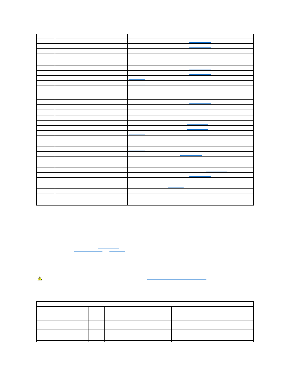
The following table lists the codes for the front panel diagnostic indicators, gives probable causes, and suggests corrective actions.
1-2-1
Programmable interval timer
Run the System Board Devices tests in the
1-2-2
Direct memory access (DMA) initialization failure
Run the System Board Devices tests in the
1-2-3
DMA page register read/write failure
Run the System Board Devices tests in the
1-3
Video Memory Test failure
Run the VESA/VGA Interface tests in the
.
1-3-1
through 2-
4-4
RIMMs not being properly identified or used
3-1-1
Slave DMA register failure
Run the System Board Devices tests in the
3-1-2
Master DMA register failure
Run the System Board Devices tests in the
3-1-3
Master interrupt mask register failure
Contact Dell
for technical assistance.
3-1-4
Slave interrupt mask register failure
Contact Dell
for technical assistance.
3-2-2
Interrupt vector loading failure
Contact Dell
for technical assistance.
3-2-4
Keyboard Controller Test failure
Run the Keyboard tests in the
. Otherwise,
contact Dell
for technical
assistance.
3-3-1
NVRAM power loss
Run the System Board Devices tests in the
3-3-2
NVRAM configuration
Run the System Board Devices tests in the
3-3-4
Video Memory Test failure
Run the VESA/VGA Interface tests in the
.
3-4-1
Screen initialization failure
Run the VESA/VGA Interface tests in the
.
3-4-2
Screen retrace failure
Run the VESA/VGA Interface tests in the
.
3-4-3
Search for video ROM failure
Run the VESA/VGA Interface tests in the
.
4-2-1
No timer tick
Contact Dell
for technical assistance.
4-2-2
Shutdown failure
Contact Dell
for technical assistance.
4-2-3
Gate A20 failure
Contact Dell
for technical assistance.
4-2-4
Unexpected interrupt in protected mode
Contact Dell
for technical assistance.
4-3-1
Memory failure above address 0FFFFh
Run the System Memory tests in the
4-3-3
Timer-chip counter 2 failure
Contact Dell
for technical assistance.
4-3-4
Time-of-day clock stopped
Contact Dell
for technical assistance.
4-4-1
Serial or parallel port test failure
Run the Serial Ports and the Parallel Ports tests in the
.
4-4-2
Failure to decompress code to shadowed memory
Run the System Board Devices tests in the
5-2-2-1
Mismatch Rambus dynamic random-access memory
(RDRAM) device count; unsupported RIMM device
count or technology
Verify that both RIMM sockets contain a RIMM or Rambus continuity module (RCM). If the
problem recurs, replace the RIMM in socket B (if any), then the RIMM in socket A. If the
problem is still not resolved,
contact Dell
for technical assistance.
5-2-2-2
Mismatch channel pair
5-2-2-3
RDRAM levelization failure
Verify that both RIMM sockets contain a RIMM or RCM. If the problem recurs, replace the
RIMM in socket B (if any), then the RIMM in socket A. If the problem is still not resolved,
contact Dell
for technical assistance.
CAUTION:
Before servicing any components inside your computer, see "
Safety First—For You and Your Computer
."
Front-Panel Diagnostic Indicator Codes
Power
Indicator
Code
Hard
Drive
Indicator
Code
Cause
Action
Solid green
N/A
Power is on, and the computer is operating
normally.
No corrective action is required.
Blinking green
Blank
The computer is in the suspended state
(Windows 2000 only).
Push and release the power button, move the mouse, or
press a key on the keyboard to bring the computer out of
the suspended state.