Video connector, Keyboard and mouse connectors – Dell PowerEdge 4400 User Manual
Page 39
Keyboard and Mouse Connectors
The system uses a Personal System/2 (PS/2)-style keyboard and supports a PS/2-compatible mouse. Cables from both devices attach to 6-pin,
miniature Deutsche Industrie Norm (DIN) connectors on the back panel of your computer.
Mouse driver software can give the mouse priority with the microprocessor by issuing IRQ12 whenever a new mouse movement is detected. The
driver software also passes along the mouse data to the application program that is in control.
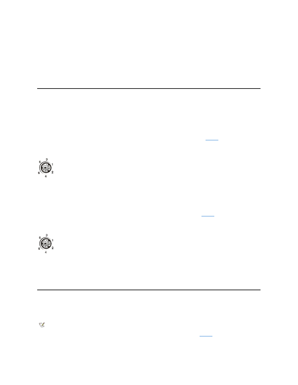
Keyboard Connector
If you reconfigure your hardware, you may need pin number and signal information for the keyboard connector.
illustrates the pin numbers
for the keyboard connector and defines the pin assignments and interface signals for the keyboard connector.
Figure 4. Pin Numbers for the Keyboard Connector
Mouse Connector
illustrates the pin numbers for
the mouse connector, and defines the pin assignments and interface signals for the mouse connector.
Figure 5. Pin Numbers for the Mouse Connector
Video Connector
The system uses a 15-pin high-density D-subminiature connector on the back panel for attaching a video graphics array (VGA)-compatible
monitor to your computer. The video circuitry on the system board synchronizes the signals that drive the red, green, and blue electron guns in the
monitor.
If you reconfigure your hardware, you may need pin number and signal information for the video connector.
illustrates the pin numbers for
the video connector, and defines the pin assignments and interface signals for the video connector.
Figure 6. Pin Numbers for the Video Connector
9
PD7
I/O
Printer data bit 7
10
ACK#
I
Acknowledge
11
BUSY
I
Busy
12
PE
I
Paper end
13
SLCT
I
Select
14
AFD#
O
Automatic feed
15
ERR#
I
Error
16
INIT#
O
Initialize printer
17
SLIN#
O
Select in
18-25
GND
N/A
Signal ground
Pin
Signal
I/O
Definition
1
KBDATA
I/O
Keyboard data
2
NC
N/A
No connection
3
GND
N/A
Signal ground
4
FVcc
N/A
Fused supply voltage
5
KBCLK
I/O
Keyboard clock
6
NC
N/A
No connection
Shell
N/A
N/A
Chassis ground
Pin
Signal
I/O
Definition
1
MFDATA
I/O
Mouse data
2
NC
N/A
No connection
3
GND
N/A
Signal ground
4
FVcc
N/A
Fused supply voltage
5
MFCLK
I/O
Mouse clock
6
NC
N/A
No connection
Shell
N/A
N/A
Chassis ground
NOTE: Installing a video card automatically disables the system's integrated video subsystem.