Installing system board options – Dell PowerEdge 1650 User Manual
Page 40
Back to Contents Page
Installing System Board Options
Dell™ PowerEdge™ 1650 Systems Installation and Troubleshooting Guide
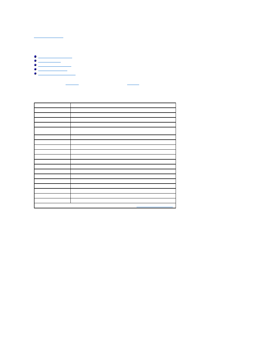
This section describes how to install expansion cards, memory modules, a microprocessor, or a ROMB card. This section also includes instructions for replacing
the system battery. Use
to locate the system board features.
describes the system board connectors and sockets.
Figure 6-1. System Board Connectors and Sockets
Table 6-1. System Board Connectors and Sockets
Connector or Socket
Description
BACKPLANE
SCSI backplane board connector
BANKn_DIMM_x
Memory module sockets
BATTERY
System battery connector
CDROM
CD drive connector
EMBEDDED_REMOTE_
ASSISTANT
Connector for optional server management card (when available)
ERA_NIC
server management port connector (when available)
ETHERNET_USBn
USB (top) and NIC connectors
FANn
Cooling fan power connectors
FLOPPY
Diskette drive connector
FRONT PANEL
System control panel connector
IDE
IDE drive connector
IDE_POWER
IDE drive power connector
KYBD_MOUSE
Mouse (top) and keyboard connectors
POWER
Power connector
PROCESSOR n
Microprocessor sockets
RAID
Socket for optional ROMB card
REAR_ID
cable management arm system status connector
RISER
PCI riser board connector
SCSI_B
External SCSI connector
NOTE:
For the full name of an abbreviation or acronym used in this table, see "
Abbreviations and Acronyms
."