Dell UPS 10000R User Manual
Page 27
27
Installation
|
NOTE:
For Europe, the emergency switch requirements are detailed in Harmonized document HD-384-48 S1,
“Electrical Installation of the Buildings, Part 4: Protection for Safety, Chapter 46: Isolation and Switching.”
REPO Connections
Wire Function
Terminal Wire Size Rating
Suggested Wire Size
REPO
4–0.32 mm
2
(12–22 AWG)
0.82 mm
2
(18 AWG)
NOTE:
The pins must be open to keep the UPS running. If the UPS shuts down because the REPO connector
pins are shorted, restart the UPS by re-opening the REPO connector pins and turning on the UPS manually.
Maximum resistance in the shorted loop is 10 ohm.
NOTE:
Always test the REPO function before applying your critical load to avoid accidental load loss.
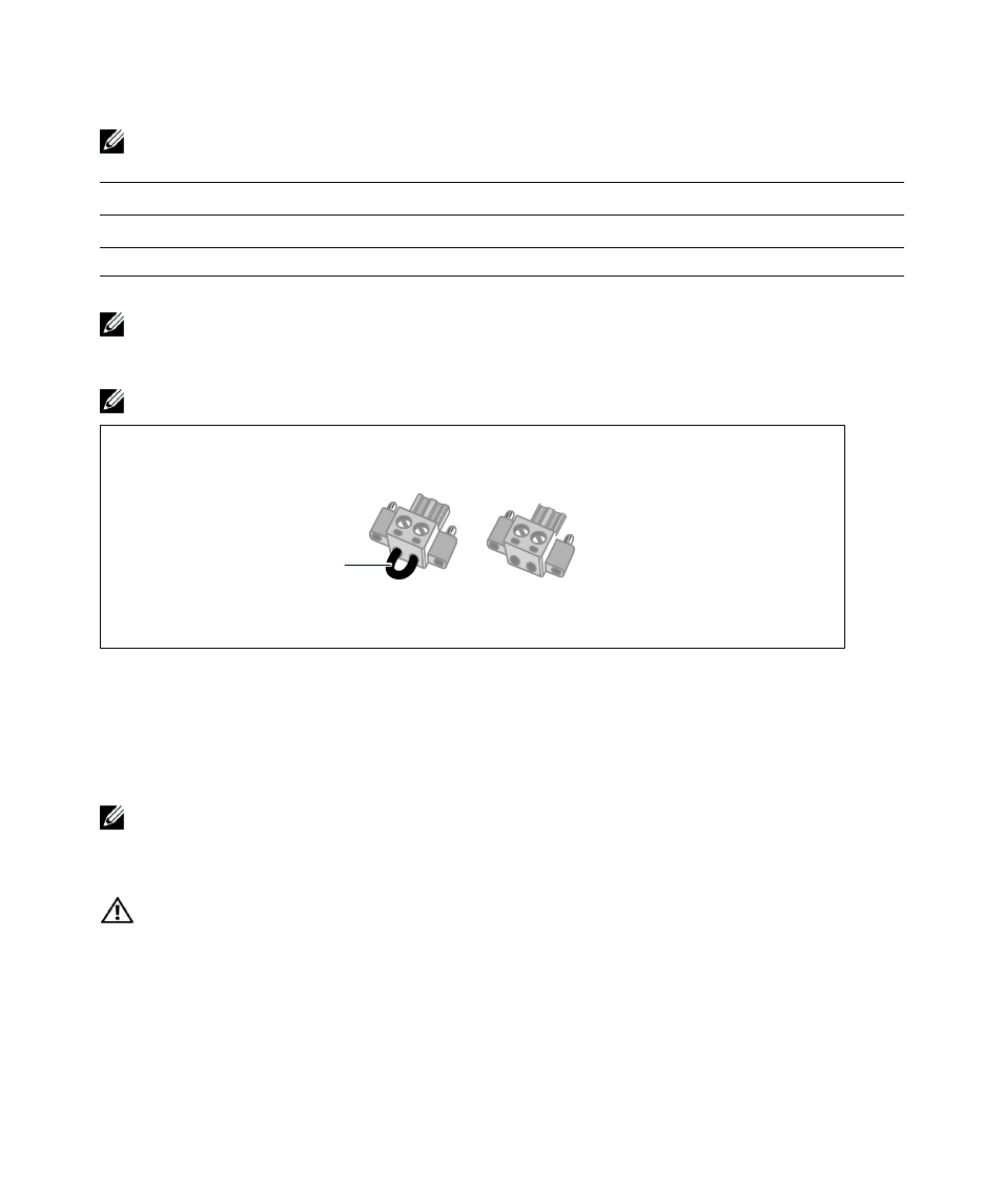
NOTE: Remove
jumper if installed
Figure 18. REPO Connector
To install the REPO switch:
1
Verify that the UPS is off and disconnected from utility power.
2
Remove the REPO connectors from the accessory box.
NOTE:
Verify that there is no jumper installed in the REPO connector. If a jumper is installed, remove it before
connecting to the REPO port. See Figure 18.
3
Connect the REPO connector to the REPO port labeled IN on the UPS rear panel.
CAUTION:
If you are daisy-chaining the REPO function, observe the following connection requirements to
avoid unintentional shutdown of the UPS:
S
The left pin of the REPO port labeled OUT on the first UPS must be connected to the left pin of the REPO port
labeled IN on the second UPS.
S
The right pin of the REPO port labeled OUT on the first UPS must be connected to the right pin of the REPO
port labeled IN on the second UPS.