Carrier REFRIGERANT R-410A User Manual
Page 12
12
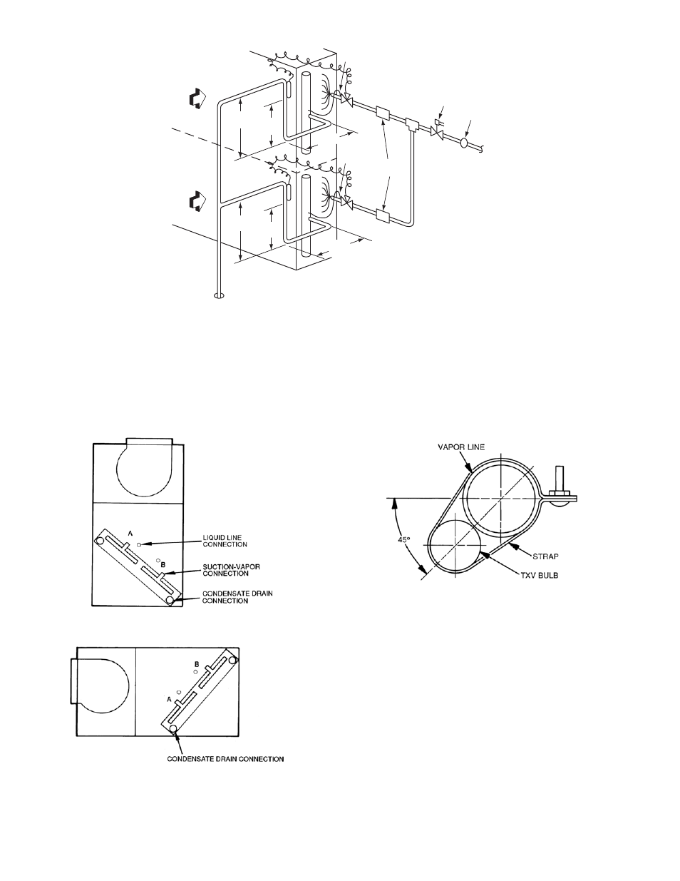
Fig. 8 — Face-Split Coil Suction and Liquid Line Piping (Typical)
Fig. 9 — Typical Evaporator Coil Connections (40RU)
Fig. 10 — TXV Sensing Bulb Location
LEGEND:
TXV – Thermostatic Expansion Valve
NOTE: Component location arrangemet shown for field installation of
sight glasses, solenoid valves, filter driers, and TXV sensing bulbs.
The TXVs and equilizer lines are factory installed.
UPPER
SPLIT
AIRFLOW
LOWER
SPLIT
AIRFLOW
15 DIAMS
MIN
10
DIAMS
8 DIAMS
MIN
TXV
SENSING
BULB
EQUALIZER LINE
SIGHT
GLASS
TXV
SOLENOID
*
VALVE
FILTER
DRIER
TXV
SENSING
BULB
TXV
8 DIAMS
MIN
15 DIAMS
MIN
10
DIAMS
INDOOR
COIL
EQUALIZER
LINE
– Not required when mated to units 38AP_025 - 060
*
FIRST ON/LAST OFF = B
VERTI CAL I NSTALLATI ON
FIRST ON/LAST OF F = A
HORIZONTAL INSTALLATIO N
LEGEND
TXV — Thermostatic Expansion Valve
NOTE: The 8 o’clock position is shown above.
- 42S (72 pages)
- 30GT (4 pages)
- 48SS060 (8 pages)
- 50ME (54 pages)
- 38AH024-034 (26 pages)
- ZC (28 pages)
- 30GA (12 pages)
- COMFORTLINK 48A2 (8 pages)
- 48HE003---006 (64 pages)
- 33ZCSECTRM (52 pages)
- 19XRV (40 pages)
- MODU-PAC 50DF (37 pages)
- 17DA (8 pages)
- SINGLE PACKAGED ELECTRIC COOLING UNITS 50GS (28 pages)
- 48JZ (N) 024-060 (30 pages)
- 30GX080-176 (8 pages)
- 50DL (24 pages)
- 50GL-A (4 pages)
- NP034-074 (72 pages)
- 40GXQ (12 pages)
- 30XA080-500 (8 pages)
- 39E (12 pages)
- 40KMQ------301 (10 pages)
- 38AE (12 pages)
- 48AW (118 pages)
- 38GXQ (28 pages)
- 48ES---A (38 pages)
- 48GL (22 pages)
- 48GH (22 pages)
- 40QA024-060 (24 pages)
- TJF004 (52 pages)
- 39LD (40 pages)
- 48DL (4 pages)
- 48/50TC04---28 (44 pages)
- 50EJ (56 pages)
- 17EX (120 pages)
- 50BA (24 pages)
- 50BB (16 pages)
- 50BB (8 pages)
- 50BJ (20 pages)
- 30H (16 pages)
- 48HJD005-007 (48 pages)
- 50ZP (6 pages)
- 50DP016 (16 pages)
- 50LJ008-014 (19 pages)