Accessing the real time clock through spi – Cypress CY14B101P User Manual
Page 17
PRELIMINARY
CY14B101P
Document #: 001-44109 Rev. *B
Page 17 of 32
Accessing the Real Time Clock through SPI
CY14B101P uses 16 registers for Real Time Clock (RTC). These
registers can be read out or written to by accessing all 16
registers in burst mode or accessing each register, one at a time.
The RDRTC and WRTC instructions are used to access the
RTC.
All the RTC registers can be read in burst mode by issuing the
RDRTC instruction and and reading all 16 bytes without bringing
the CS pin HIGH. The ‘R’ bit must be set while reading the RTC
timekeeping registers to ensure that transitional values of time
are not read.
Writes to the RTC register are performed using the WRTC
instruction. Writing RTC timekeeping registers and control
registers, except for the flag register needs the ‘W’ bit of the flag
register to be set to “1”. The internal counters are updated with
the new date and time setting when the ‘W’ bit is cleared to ‘0’.
All the RTC registers can also be written in burst mode using the
WRTC instruction.
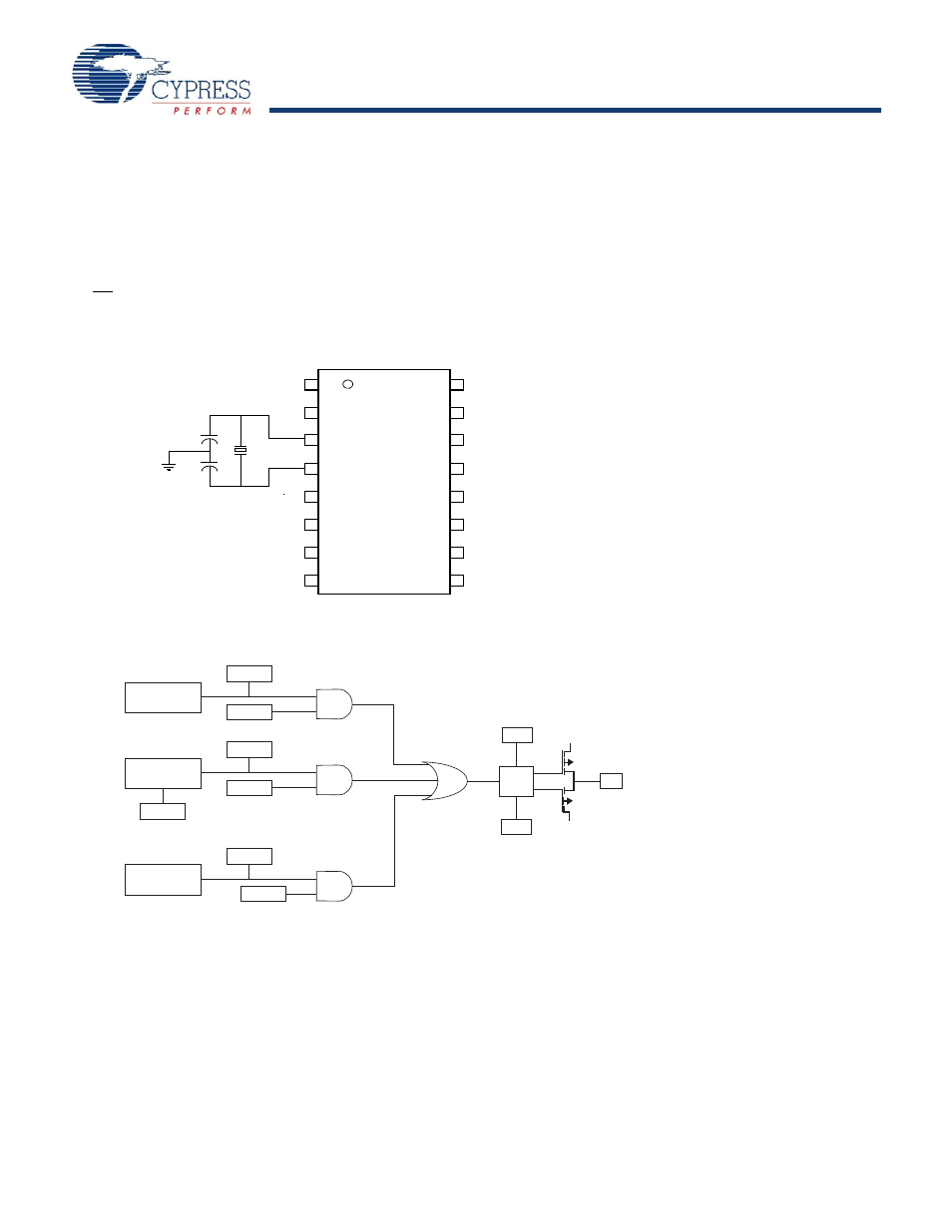
Figure 22. RTC Recommended Component Configuration
Figure 23. Interrupt Block Diagram
Recommended Values
Y1 = 32.768KHz
C
1
= 21pF
C
2
= 21pF
Xout
Xin
Y1
C2
C1
Note: The recommended values for C1 and C2 include
board trace capacitance.
Watchdog
Timer
Power
Monitor
Clock
Alarm
VINT
WDF
WIE
PF
PFE
AF
AIE
P/L
Pin
Driver
H/L
INT
V
CC
V
SS
WDF - Watchdog Timer Flag
WIE - Watchdog Interrupt
PF - Power Fail Flag
PFE - Power Fail Enable
AF - Alarm Flag
AIE - Alarm Interrupt Enable
P/L - Pulse Level
H/L - High/Low
Enable