Tap controller state diagram – Cypress Perform CY7C1561V18 User Manual
Page 14
CY7C1561V18, CY7C1576V18
CY7C1563V18, CY7C1565V18
Document Number: 001-05384 Rev. *F
Page 14 of 28
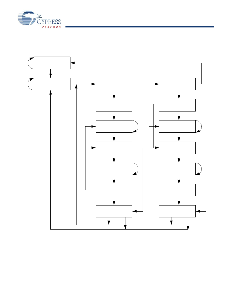
The state diagram for the TAP controller follows.
TAP Controller State Diagram
TEST-LOGIC
RESET
TEST-LOGIC/
IDLE
SELECT
DR-SCAN
CAPTURE-DR
SHIFT-DR
EXIT1-DR
PAUSE-DR
EXIT2-DR
UPDATE-DR
1
0
1
1
0
1
0
1
0
0
0
1
1
1
0
1
0
1
0
0
0
1
0
1
1
0
1
0
0
1
1
0
SELECT
IR-SCAN
CAPTURE-IR
SHIFT-IR
EXIT1-IR
PAUSE-IR
EXIT2-IR
UPDATE-IR
Note
12. The 0/1 next to each state represents the value at TMS at the rising edge of TCK.
This manual is related to the following products: