Figure 1-9, Plug into its connector (see figure 1-9), Figure 1-9) – Dell PowerEdge 1800 User Manual
Page 19
Rack Installation Guide
1-17
7
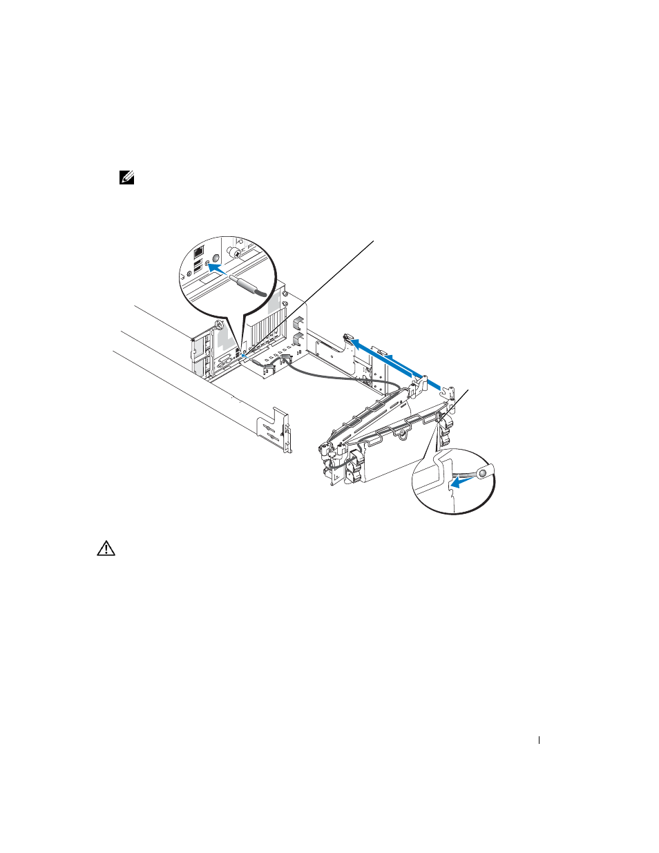
Connect the power cables to their receptacles on the system back panel.
NOTE:
Use the strain-relief loop (if available) on the back of the system to provide strain relief for
the power cables.
Figure 1-9.
Installing the System Status Indicator Cable (If Applicable)
8
Connect the power cords to their receptacles on the back panel (see Figure 1-10).
CAUTION:
Allow some slack in each cable as you route them around hinges in the cable-management
arm.
9
Attach the I/O cable connectors to their respective connectors on the system back panel.
10
Attach the I/O cable connectors to their respective connectors on the system back panel.
For details on cable connections, see your system’s Installation and Troubleshooting Guide
and your User’s Guide.
11
Route the power and I/O cables through the cable-management arm, using four loosely
secured tie-wraps (two in the middle and one on each end of the cable-management arm).
Do not fully tighten the tie-wraps at this time (see Figure 1-10).
Allow some cable slack in the cable-management arm to prevent damage to the cables.
system status
indicator cable plug
system
status
indicator