Time constant τ – Baumer CombiTemp User Manual
Page 3
Page 3
Design and specifi cations subject to change without notice
Installation Manual 5850-008
www.baumerprocess.com
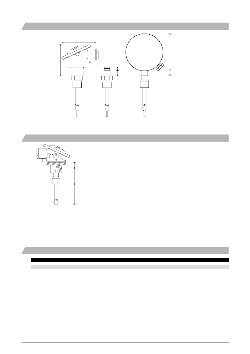
[mm]
71
76
7.5
12.5
85
11
Male Nipple G1/2A
Male Nipple G1/2A
Male Nipple G1/2A
mounted on DIN B housing
mounted on ø80 mm housing
Sensor type
Liquids
Air
Dimension
Response
Insert
0.4 m/sec.
3 m/sec.
0 m/sec.
ø6 mm tube
fast
< 1.5 sec.
< 21.4 sec.
< 135.6 sec.
ø8 mm tube
fast
< 1.5 sec.
< 33.6 sec.
< 181.0 sec.
ø10 mm tube
fast
< 1.5 sec.
< 46.8 sec.
< 238.9 sec.
ø12 mm tube
fast
< 1.5 sec.
< 59.9 sec.
< 311.4 sec.
ø6 mm tube
normal
< 6.1 sec.
< 27.2 sec.
< 137.8 sec.
ø8 mm tube
normal
< 7.6 sec.
< 47.7 sec.
< 200.9 sec.
ø10 mm tube
normal
< 11.1 sec.
< 57.8 sec.
< 270.6 sec.
ø12 mm tube
normal
< 16.2 sec.
< 70.8 sec.
< 319.8 sec.
ø8 mm tube
normal
5.6 mm
< 13.6 sec.
< 51.1 sec.
< 253.1 sec.
ø10 mm tube
normal
5.6 mm
< 28.1 sec.
< 67.0 sec.
< 271.1 sec.
ø12 mm tube
normal
5.6 mm
< 31.3 sec.
< 82.3 sec.
< 289.3 sec.
Surface sensor, fl ush mounted
< 1.0 sec.
Time Constant
τ
0.5
Dimensional Drawings - Mounting Details
Sensor inserts
DIN housing with G1/2A male nipple connection
and sensor insert
Note {8}
Housing shaft
DIN housing: 11.5 mm
ø80 housing: 6.5 mm
Calculation of insert length:
When ordering an insert the length must be calculated from the
formula:
Insert length = Sensor length + total body length + housing shaft
(Total body length can be calculated from the dimensional drawings on
pages 6 and 7)
Example.
Insert for a G1/2A male nipple sensor in a DIN housing, 100 mm
sensor tube, normal response sensor tip:
Housing shaft = 11.5 mm
Total body length = 27.5 + 12.5 = 40 mm (see page 6)
Sensor length = 100 mm
This insert must be ordered with a 151.5 mm sensor tube.
Housing shaft {8}
Total body length
Sensor length (L)